support hotline
0577-57572522
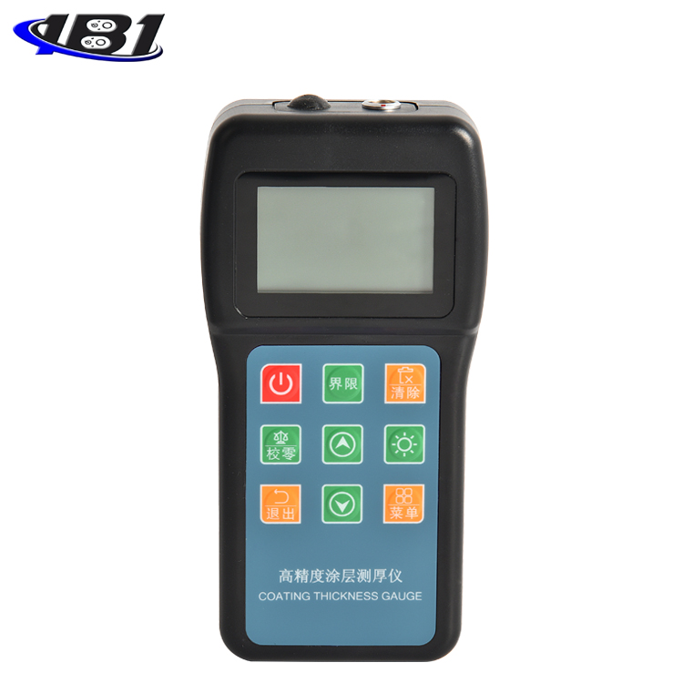

This instrument is a portable measuring instrument that can quickly and accurately measure the thickness of coatings and coatings without damage. It can be used in the laboratory and engineering field. By using different probes, you can also meet the needs of a variety of measurements. This instrument can be widely used in manufacturing, metal processing industry, chemical industry, commodity inspection and other testing fields. It is an indispensable instrument for material protection professionals.
This instrument meets the following standards:
GB / T 4956─1985 Non-magnetic coating thickness measurement on magnetic metal substrate Magnetic method
GB / T 4957─1985 Thickness measurement of non-conductive cover on non-magnetic metal substrate Eddy current method
JB / T 8393─1996 Magnetic and eddy current type coating thickness measuring instrument
JJG 889─95 \"Reluctance Thickness Gauge\"
JJG 818─93 \"Eddy current thickness gauge\"
Features:
Both magnetic and eddy current thickness measurement methods are used, which can measure the thickness of the non-magnetic covering layer on the magnetic metal substrate and the thickness of the non-conductive covering layer on the non-magnetic metal substrate;
10 kinds of probes can be used (F400, F1, F1 / 90 °, F5, F10, N400, N1, N1 / 90 °, CN02, N10);
Has two measurement methods: continuous measurement method (CONTINUE) and single measurement method (SINGLE);
Has two working modes: direct mode (DIRECT) and group mode (A-B);
Set five statistics: average (MEAN), maximum (MAX), minimum (MIN), number of tests (NO.), Standard deviation (S.DEV);
The instrument can be calibrated by single-point calibration and two-point calibration, and the system error of the probe can be corrected by the basic calibration method;
With storage function: 495 measured values can be stored;
With delete function: delete the single suspicious data appearing in the measurement, or delete all the data in the storage area, in order to make a new measurement;
Limits can be set: the measured values outside the limits can be automatically alarmed;
Power supply undervoltage indication function;
Buzzer sounds during operation;
With error prompt function, error prompt can be displayed through on-screen display or beep sound;
There are two shutdown modes: manual shutdown mode and automatic shutdown mode;
● The host computer can be connected to the computer by installing software. After connection, data download, storage, and printing can be completed through computer operation, which is fast and convenient.
This instrument uses two thickness measurement methods, magnetic and eddy current, to non-destructively measure the thickness of non-magnetic coatings (such as aluminum, chromium, copper, enamel, Rubber, paint, etc.) and the thickness of non-conductive coatings on non-magnetic metal substrates (such as copper, aluminum, zinc, tin, etc.) (such as: enamel, rubber, paint, plastic, etc.).
a) Magnetic method (F-type probe)
When the probe is in contact with the cover layer, the probe and the magnetic metal substrate form a closed magnetic circuit. Due to the presence of the non-magnetic cover layer, the magnetic resistance of the magnetic circuit changes. The thickness of the cover layer can be derived by measuring the change.
b) Eddy current method (N-type probe)
An high-frequency alternating current is used to generate an electromagnetic field in the coil. When the probe is in contact with the cover layer, a metal substrate is produced.
Generate electric eddy current and generate feedback effect on the coil in the probe. The thickness of the cover layer can be derived by measuring the magnitude of the feedback effect.
degree.
Figure 1-1 Basic working principle of magnetic method Figure 1-2 Basic working principle of eddy current method
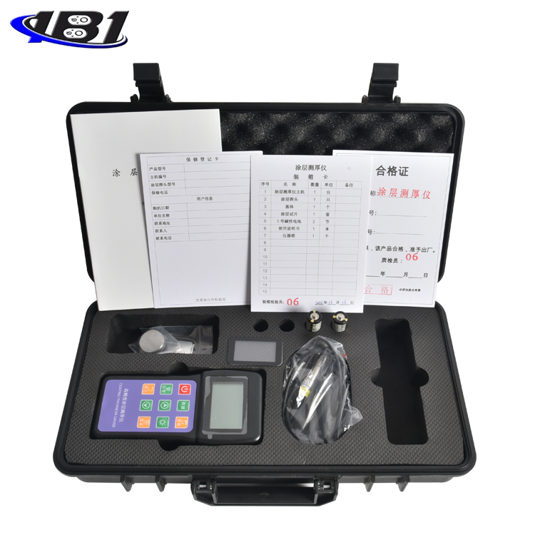
1.2ConfigurationChecklist
|
Name |
Number |
Note |
|---|---|---|
|
Host |
1 set |
The standard configuration |
|
F1 probe |
1 |
|
|
Standard film |
5 tablets |
|
|
Matrix |
1 piece |
|
|
Product packing box |
1 |
|
|
user's manual |
1 copy |
|
|
Probes for other uses |
Option |
|
1.2.1Probe view and name
1. Positioning sleeve 2. V-shaped port 3. Loading sleeve 4. Wiring 5. Plug 6. Lock nut
1.2.2 Host view and name of each part
1.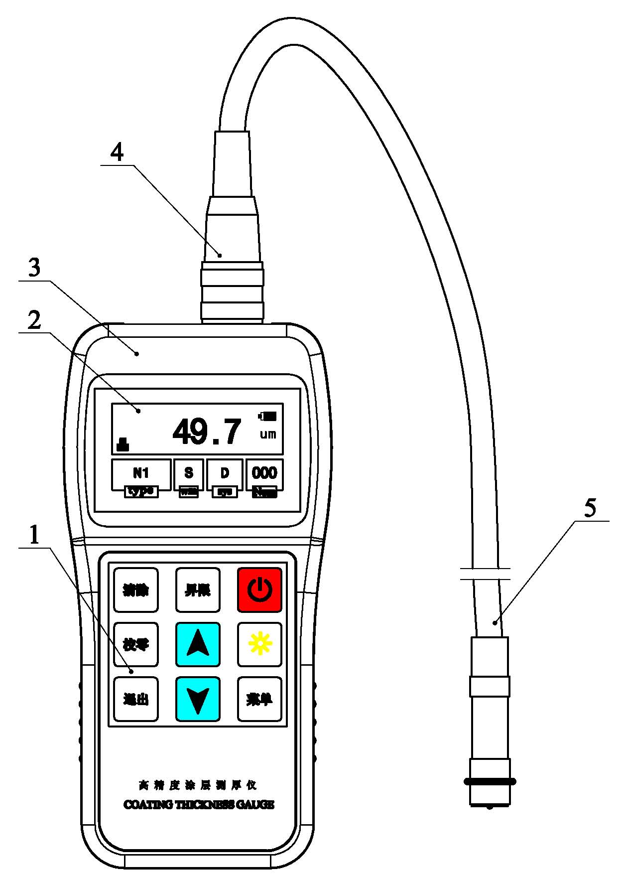 Instrument host 2. Display 3. Keyboard 4. Probe socket 5. Instrument probe
1.2.3screen display
1. Data display 2 Measurement method 3. Probe type index
4. Storage record count indication 5. Measurement unit 6. Battery level indication.
1.3.1Measurement range and measurement error(See Appendix 1)
1.3.2Use environment
Temperature: -10 ℃ ~ 40 ℃
Humidity: 20% ~ 90% RH
No strong magnetic field environment
1.3.3power supply
2 × 1.5V AA (No. 5)
Overall dimensions: 1250mm × 67 mm × 31 mm
Weight: about 400g
Before using this instrument, please read Chapter 3 (Calibration) and Chapter 4 (Factors Affecting Measurement Accuracy) carefully.
a) Have the parts to be tested ready (see Chapter 4);
b) Insert the probe plug into the probe socket of the host and tighten the lock nut;
c) Put the probe in the open space, press \"\" key once to start up;
d) The instrument self-test shows the type of probe installed. The interface is as follows:
e) Check the battery voltage; if the battery voltage is too low, the instrument will automatically shut down.
Note 1: When the battery symbol is displayed full, it indicates that the battery voltage is normal; when the space is displayed, it indicates that the battery voltage has fallen, and the battery should be replaced immediately;
Note 2: Remove the electric battery when it is not used for a long time.
Under normal circumstances after the self-test, the measured value before the last shutdown is displayed; as shown below:
|
Windows |
Display content |
Meaning |
Note |
|
Type Probe type |
NON-FERROUS |
N-type probe |
|
|
FERROUS |
F-type test |
||
|
Sys Way of working |
D |
Direct measurement |
|
|
APPL 01 |
Group measurement method 1 |
||
|
APPL 02 |
Group measurement method 2 |
||
|
APPL 03 |
Group measurement method 3 |
||
|
APPL 04 |
Group measurement method 4 |
||
|
APPL 05 |
Group measurement method 5 |
||
|
Num Storage unit |
1-99 |
Number of cells being stored |
5 groups in total |
f) whether it is necessary to calibrate the instrument, and if necessary, select an appropriate calibration method (see Chapter 4);
g) measurement
Quickly touch the probe perpendicular to the test surface and lightly press the probe positioning sleeve. With a beep, the screen displays the measured value. Lift the probe for the next measurement
g) shutdown
Without any operation, the instrument will automatically shut down after about 1 ~ 2min. Press the \"\" key once to shut down immediately.
Note: 1. If the probe is not placed stably during the measurement, an obvious suspicious value is displayed. Press CLEAR to delete
The value
2.2Various functions and operation methods
Menu list organization chart
|
Data Statistic Data statistics |
Total: |
Total number of statistical samples |
|
Mean |
average value |
|
|
Max |
Max |
|
|
Min |
Minimum value |
|
|
Sdev |
standard deviation |
|
|
Measuring Mode measurement method |
Single |
Single measurement |
|
Continue |
Continuous measurement |
|
|
Working Mode Way of working |
DIRECT |
Direct measurement |
|
APPL 1 |
Group measurement method 1 |
|
|
APPL 2 |
Group measurement method 2 |
|
|
APPL 3 |
Group measurement method 3 |
|
|
APPL 4 |
Group measurement method 4 |
|
|
APPL 5 |
Group measurement method 5 |
|
|
Measuring Unit Unit of measure |
μm |
Metric unit |
|
mils |
Imperial units |
|
|
Delete Files Delete Files |
APPL 1 |
Delete group measurement file 1 |
|
APPL 2 |
Delete group measurement file 2 |
|
|
APPL 3 |
Delete group measurement file 3 |
|
|
APPL 4 |
Delete group measurement file 4 |
|
|
APPL 5 |
Delete group measurement file 5 |
|
|
ViewData File View data record contents |
APPL 1 |
View the corresponding group mode Recorded data |
|
APPL 2 |
||
|
APPL 3 |
||
|
APPL 4 |
||
|
APPL 5 |
||
|
About Software Software information |
Version |
Instrument software version number |
|
Code |
Instrument factory code |
|
|
SN |
Instrument serial number |
|
2.2.1 Measurement method (single measurement continuous measurement)
Single measurement-each time the probe touches the DUT, a measurement result is displayed with a beep;
Continuous measurement ——Don’t lift the probe for dynamic measurement, there will be no sound during the measurement, and the measurement result will flash on the screen;
The conversion method of the two methods is as follows: in the power-on state, after pressing the\"\" ENTER\"key, the on-screen menu is displayed. Select and press the\"\"\"\"\"\"\"\"\" key to select the reverse display item after the\"\" Measuring Mode \" Then press the\"\" ENTER\"key to enter the measurement mode setting interface. Press the\"\"\"\"\"\"\"\"button to select the measurement mode. \"Key to return to the main display interface in turn, and start to enter a new measurement mode for measurement.
2.2.2Working mode (direct mode group mode)
DIRECT method-This method is used for random measurement. The measurement value is temporarily stored in the memory unit (a total of 99 storage units). When 99 storage units are filled, the new measurement value will replace the old one. The measured values, that is, the 99 most recent measured values are always involved in statistical calculations.
Group mode (APPL) ─ This mode is convenient for users to record the test data in batches. One group can store up to 99 values, and a total of five groups can store 495 values. When there are 99 values in each group, \"num \" on the screen will display\"99\". At this time, measurement can still be performed, but the measured values are only displayed, not stored, and they do not participate in statistical calculation. If necessary, you can delete this group of data and make a new measurement.
Each group has a calibration value, that is, each data in the group is measured based on this calibration value. Limits can be set in each group, and the measurement results in the group can be identified and alarmed. In the group mode, each measurement value is automatically entered into the statistical program to participate in the statistical calculation. Because the group method can store several sets of measurement data based on different calibration values, this method is particularly suitable for field measurement.
Note: All measured values are automatically entered into statistics (the program is not applicable to F1 / 90 ° C and N1 / 90 ° C probes).
The two conversion methods are:
After the instrument is turned on, it will automatically enter the direct working mode, and the working mode area will display \"D \". Press the\"\" ENTER\"key, and then press the\"\"\"\"\"\"\"\"key to select the highlighted item in the\" Working Mode\"and then press the\"\"ENTER\" key to enter the working mode setting interface, press \"\" \"\" Key to select the working mode, press \"ESC \" key to return to the main display interface. The instrument enters the group mode, and the\"\" sys\"working mode area displays \" APPL 01 \"; \" APPL 02 \"... \" APPL 05 \";
2.2.3Unit System Conversion (Metric and English)
The conversion method of the metric system and the imperial system is: under the power-on state, after pressing the\"\" ENTER\"key, the on-screen display menu, select and press the\"\"\"\"\"\"\"\"\"\"key to select the reverse display item after\"\"Measuring Unit \" Press \"ENTER \" key to enter the unit system setting interface, press \"\" \"\" key to select the measurement mode, μm (metric); mils (imperial), press \"ESC \" key in order Exit to the main display interface and start entering a new measurement mode
2.2.4Calculations
This instrument automatically performs statistical processing on measured values. It needs at least three measured values to generate 5 statistical values: average (MEAN), standard deviation (S.DEV), number of tests (No.), and maximum test value (MAX). ), The minimum test value (MIN).
a) Measured values participating in statistical calculations
所有 In the direct mode, all measured values (including measured values before shutdown) participate in statistical calculations.
Note: When 99 storage units are filled, the new measurement value will replace the old measurement value. The storage area stores the latest 99 measured values.
⊙ In group mode, the measurement values participating in the statistical calculation are limited to the data in this group.
Note: When there are 99 values in each group, although the measurement can continue, the statistical value cannot be modified. When needed, the memory unit can be cleared and new measurements can be taken;
b) Display statistics
Press \"ENTER \" key, operate \"\" \"\" key to select the highlighted item and then press\"\" Data Statistic \", then press \" ENTER \"key, all 5 statistical values will be displayed.
2.2.5Storage
In the group mode, the measured values are automatically stored in the memory unit. A group can store up to 99 values. A total of five groups can store 495 values.
2.2.6delete
⊙ Delete the current measurement
No matter in direct mode or group mode, as long as the measured value is displayed, press the \"CLEAR \" key once, and the current measured value has been deleted with a beep.
⊙ Delete all measured values, statistical values, and two-point calibration values in direct mode
In the direct mode measurement value display state, press the \"CLEAR \" key twice. With a long beep, all measurement values, statistical values, and two-point calibration values in the direct mode have been deleted.
⊙ Delete all measured values, statistical values, calibration values, limit values in a group
Press \"ENTER \" key, operate \"\" \"\" key to select the highlighted item in \"Delete Files \" and press \"ENTER \" key to enter the delete interface, operate \"\" \"\" Key After selecting the group number, press \"CLEAR \" key. With a long beep, all measured values, statistical values, calibration values, and limit values in this group have been deleted.
2.2.7Set limits
a) Press the\"\" LIMITS \"key to display the previously set upper limit, and then use the and keys to set the new upper limit.
b) Press the\"\" LIMITS \"key again to display the previously set lower limit, and then use the and keys to set the new upper limit.
Tips: 1. Boundary is only valid in group mode;
2. Buzzer sounds for test results outside the limits;
3. Out-of-bounds test results are stored and statistically calculated together with other test results.
4. The closeness of the upper and lower limits is limited. When the upper limit value is 200 μm or more, the minimum close degree of the upper and lower limits is 3% of the upper limit, and when the upper limit value is 200 μm or less, the minimum close degree of the upper and lower limits is 5 μm.
2.2.8List of operations
Table 3-1 Operation list
|
Key name |
Features |
Remark |
|
ZERO |
Zero calibration |
3.3.1 |
|
LIMIT |
Set limits |
2.2.7 |
|
CLEAR |
Delete test value, statistical value, limit, calibration value |
2.2.6 |
|
Digital adjustment |
||
|
On and off |
2.1 |
|
|
+ |
Used to enter the basic calibration state |
3.4 |
* The numbers given in the remarks column are the sections in this manual that explain this function.
2.2.9Notes on measurements and errors
⊙ If proper calibration has been performed, all measured values will remain within a certain error range (see Appendix 1);
⊙ From a statistical point of view, one reading is unreliable. Therefore any measurement value displayed by the instrument is the average of five\"invisible\" measurements. These five measurements are made by the probe and the instrument in a fraction of a second;
⊙ In order to make the measurement more accurate, a statistical program can be used to measure multiple times at one point. The gross error is deleted by CLEAR. The thickness of the final coating is:
CH = M + S + δ
Where: CH: coating thickness
M: average value of multiple measurements
S: standard deviation
δ: instrument tolerance
3Calibration of the instrument
To make the measurement accurate, the instrument should be calibrated at the measurement location.
3.1Calibration standards (including foil and substrate)
Either a foil of known thickness or a specimen of known cover thickness can be used as a calibration standard. Referred to as standard film.
a) Calibration foil
For magnetic methods,\"foil\" means non-magnetic metal or non-metal foil or gasket. For the eddy current method, plastic foil is usually used. \"Foil \" facilitates calibration on curved surfaces and is more suitable than standard films with overlays.
b) Covered standard film
As the standard sheet, a cover layer of known thickness, uniform and firmly bonded to the substrate is used. For magnetic methods, the cover is non-magnetic. For the eddy current method, the cover is non-conductive.
3.2Matrix
a) For the magnetic method, the magnetic properties and surface roughness of the base metal of the standard sheet should be similar to those of the base metal of the part to be tested. For the eddy current method, the electrical properties of the standard substrate metal should be similar to the electrical properties of the substrate metal to be tested. In order to verify the applicability of the standard film, the base metal of the standard film can be compared with the readings measured on the base metal of the piece to be tested.
b) If the thickness of the metal substrate of the part to be tested does not exceed the critical thickness specified in Table 1, two methods can be used for calibration:
1) Calibrate on a metal standard with the same thickness as the metal substrate of the part to be tested;
2) Use a metal pad metal standard or test piece of sufficient thickness and similar electrical properties, but there must be no gap between the base metal and the pad metal. For specimens with coatings on both sides, the pad method cannot be used.
c) If the curvature of the covering layer to be measured has not been calibrated on a plane, the curvature of the standard sheet with the covering layer or the curvature of the base metal placed under the calibration foil shall be the same as the curvature of the specimen.
There are three calibration methods used in this instrument: zero-point calibration, two-point calibration, and calibration on sandblasted surfaces. The two-point calibration method is divided into one test strip method and two test strip method. There is also a basic calibration for the probe. The calibration method for this instrument is very simple.
3.3.1Zero calibration
Suitable for all probes except CN02.
a) Take a measurement on the substrate and the screen displays <×. × m>.
b) Press ZERO key, the screen will display. Calibration is complete and measurement is ready.
c) Repeat the above steps a and b to obtain a more accurate zero point and high measurement accuracy. Measurement can be performed after the zero calibration is completed.
3.3.2.1 One test piece method
Suitable for all probes except CN02. This calibration method is suitable for high-precision measurement and small workpieces, hardened steel, alloy steel.
a) Zero calibration first (as above).
b) Perform a measurement on a standard film whose thickness is approximately equal to the expected thickness of the overlay to be measured. The screen displays <××× m>.
c) Use the key to correct the reading to the standard value. Calibration is complete and measurement is ready.
Note: 1. Even if the displayed result matches the standard slice value, pressing the key is essential.
For example, press once. This applies to all calibration methods.
2. If you want to perform two-point calibration more accurately, repeat steps b and c to improve the accuracy of calibration.
Reduce accidental errors.
3. When using F5 and F10 probes, when measuring metal coatings, use the two-point calibration method for calibration.
3.3.2.2 Two test piece method
Suitable for all probes except CN02. The thickness of the two standard films is at least three times different. The thickness of the overlay to be measured should be between two calibration values. This method is particularly suitable for rough sandblasted surfaces and high-precision measurements.
a) Zero the value first.
b) Take a measurement on a thin standard and use the key to correct the reading to the standard value.
c) Immediately take a measurement on a thick sample and use the key to correct the reading to the standard.
value. Calibration is complete and measurement is ready.
3.3.2.3 Calibration on sandblasted surfaces
The characteristics of the sand blasting surface cause the measured value to deviate greatly from the true value, and the thickness of the cover layer can be roughly determined by the following method.
method one:
a) The instrument should be calibrated on a smooth surface with the same radius of curvature as the substrate using 3.3.1 or 3.3.2.1.
b) Measured about 10 times on the uncoated surface subjected to the same sandblasting to obtain the average value Mo.
c) Then, measure 10 times on the coated surface to obtain the average Mm.
d) (Mm—Mo) ± S is the thickness of the cover layer.
Among them, S (standard deviation) is the larger of SMm and SMo.
Method Two:
a) Measure with single measurement in direct mode.
b) First calibrate the instrument using the two test strip method.
c) Measure 5-10 times on the sample. Press the STATS key, and the average value in the statistical value is the thickness of the coating.
3.3.2.4 Calibration method for chrome plating on copper
Suitable for N400, N1 and N1 / 90 ° probes, and uses special calibration standards.
⊙A test strip method must be used.
⊙Use special standard films marked with \"CHROME ON COPPER\".
3.3.2.5 Calibration method of CN02 probe
CN02 is a flat measuring head that is only suitable for measuring the thickness of a copper plate or copper foil with a smooth surface.
a) After starting up, place the CN02 probe stably on the 5.0mm copper block that comes with the machine and press the ZERO key. The screen displays \"OO\"
b) make a measurement on a standard film;
c) Use the key to correct the reading to the standard value. Calibration is complete and measurement can begin.
d) The measurement of double-sided copper-clad boards should be calibrated with double-sided copper-clad standards.
Note: In the case of extreme temperature changes, such as outdoor operation in winter or summer, calibration should be performed on a standard film close to the thickness of the foil to be measured. The ambient temperature during calibration should be the same as the ambient temperature during use.
note:
1. The following conditions must be recalibrated.
时 An incorrect value was entered during calibration
Operation error
测 Probe changed
2. In the direct mode, if an incorrect calibration value is entered, a measurement should be taken immediately, and then a calibration will be performed to obtain a new value to eliminate the incorrect value.
3. There can be only one calibration value in each group of units.
4. Both zero and two-point calibrations can be repeated multiple times to obtain more accurate calibration values and improve measurement accuracy. However, once there is one measurement in this process, the calibration process ends.
3.3.3Modify calibration values in group FX
Recalibration can only be performed after deleting all data and calibration values in the group unit. Otherwise, an E20 error code and an alarm will sound. This method must be used after changing the probe!
3.4 Correction of basic calibration
It is necessary to change the basic calibration if:
____ The probe tip is worn.
____ The new probe.
____ Special purpose.
In the measurement, if the error obviously exceeds the given range, re-calibrating the probe characteristics is called basic calibration. The probe can be recalibrated by entering 6 calibration values (1 zero and 5 thickness values).
a) Press and hold the key while the instrument is turned off, and then press the key until a long beep is heard to enter the basic calibration state;
b) Zero the value first. It can be repeated several times in succession to obtain an average value of multiple calibrations, which can improve the accuracy of calibration;
c) Use the standard sheet, in the order of increasing thickness, it can be done multiple times on one thickness. Each thickness should be at least 1.6 times the previous thickness, ideally 2 times. For example: 50, 100, 200, 400, 800 μm. The maximum value should be close to but below the maximum measuring range of the probe;
Note: Each thickness should be at least 1.6 times the previous thickness, otherwise the basic calibration is considered a failure.
d) After entering 6 calibration values, measure the zero point, the instrument will automatically shut down, and the new calibration value has been stored in the instrument. When the instrument is turned on again, the instrument will operate at the new calibration value.
4Factors affecting measurement accuracy
Table 4-1 Related factors
|
Measurement methods Influencing factors |
Magnetic method |
Eddy current method |
|
Base metal magnetic |
▲ |
|
|
Electrical properties of base metal |
▲ |
|
|
Base metal thickness |
▲ |
▲ |
|
Edge effect |
▲ |
▲ |
|
Curvature |
▲ |
▲ |
|
Deformation of the specimen |
▲ |
▲ |
|
Surface roughness |
▲ |
▲ |
|
magnetic field |
▲ |
|
|
Attachment |
▲ |
▲ |
|
Probe pressure |
▲ |
▲ |
|
Probe orientation |
▲ |
▲ |
▲ ------ indicates that it has an impact
4.2Explanation of influencing factors
a) Base metal magnetic
The thickness measurement by the magnetic method is affected by the magnetic change of the base metal (in practical applications, the magnetic change of low-carbon steel can be considered to be slight). Calibrate the instrument with a standard film; you can also use the test specimen to be coated for calibration.
b) Electrical properties of base metal
The conductivity of the base metal affects the measurement, and the conductivity of the base metal is related to its material composition and heat treatment method. Calibrate the instrument using a standard sheet with the same properties as the test specimen base metal.
c) Base metal thickness
Each instrument has a critical thickness of the base metal. Above this thickness, the measurement is not affected by the thickness of the base metal. See Table 1 for the critical thickness values of this instrument.
d) Edge effect
This instrument is sensitive to sudden changes in the surface shape of the test piece. Therefore, it is not reliable to measure near the edge or inside corner of the test piece.
e) curvature
The curvature of the test piece has an influence on the measurement. This effect always increases significantly as the radius of curvature decreases. Therefore, measurement on the surface of a curved test piece is unreliable.
f) Deformation of the test piece
The touch probe deforms the soft cover specimens, so reliable data is measured on these specimens.
g) Surface roughness
The surface roughness of the base metal and the cover has an influence on the measurement. As the degree of roughness increases, the effect increases. Rough surfaces can cause systematic and occasional errors. Each measurement should increase the number of measurements at different locations to overcome this occasional error. If the base metal is rough, you must also check the zero point of the instrument on several uncoated base metal specimens with similar roughness; or dissolve and remove the cover with a solution that does not corrode the base metal, and then calibrate the Zero.
g) Magnetic field
The strong magnetic fields generated by various electrical equipment around it will seriously interfere with the thickness measurement of the magnetic method.
h) Attached substances
This instrument is sensitive to those adherent substances that prevent the probe from coming into close contact with the surface of the cover. Therefore, the adherent substances must be removed to ensure that the probe of the instrument is in direct contact with the surface of the test piece.
i) Probe pressure
The amount of pressure exerted by the stylus on the test piece will affect the measured reading, so keep the pressure constant.
j) Probe orientation
How the probe is placed affects the measurement. During the measurement, the probe should be kept perpendicular to the sample surface.
4.3Rules to be followed when using the instrument
a) Base metal characteristics
For the magnetic method, the magnetic properties and surface roughness of the base metal of the standard sheet should be similar to those of the base metal of the test piece.
For the eddy current method, the electrical properties of the base metal of the standard sheet should be similar to those of the base metal of the test piece.
b) Base metal thickness
Check whether the thickness of the base metal exceeds the critical thickness. If not, use one of the methods in 3.3) for calibration.
c) edge effects
Measurements should not be made close to sudden changes in the test piece, such as edges, holes, and corners.
d) Curvature
It shall not be measured on the curved surface of the test piece.
e) Number of readings
Usually because the instrument's readings are not exactly the same, several readings must be taken in each measurement area. Local differences in the thickness of the cover also require multiple measurements in any given area, especially when the surface is roughed.
f) Surface cleanliness
Before measurement, remove any attached substances on the surface, such as dust, grease, and corrosion products, but do not remove any coating substances。
Strictly avoid collisions, heavy dust, humidity, strong magnetic fields, and oil pollution.
When the instrument is in use, when the battery voltage is too low, that is, the battery logo on the screen is empty, the battery should be replaced as soon as possible. When replacing the battery, pay particular attention to the positive and negative polarities of the battery installation.
The following error message table tells you how to identify and troubleshoot:
Table 5-1 Error message table
|
Error code |
Meaning of error code |
Causes and solutions |
|
E02 |
Damaged probe or instrument |
Repair of probes or instruments |
|
E03 |
Damaged probe or instrument |
Repair of probes or instruments |
|
E04 |
Large fluctuations in the measured value (for example when measuring on a soft cover); magnetic field effects |
When measuring on a soft cover, use an auxiliary device for measurement; keep away from strong magnetic fields |
|
E05 |
The probe is too close to the metal substrate when starting up |
Probe away from metal substrate |
|
E08 |
Damaged probe or instrument |
Repair of probes or instruments |
|
E11 |
The probe model does not match the probe model corresponding to the original data of this group |
Replace the appropriate probe Select another unused group unit Recalibrate after deletion |
|
E15 |
The zero value deviation is too large to be zeroed |
Choose the right substrate or repair the instrument |
|
E20 |
Calibration values already in this group of units |
Select another unused grouping unit or delete and recalibrate |
If the error code is not displayed and is not working properly, for example:
a) The instrument cannot be turned off automatically;
b) cannot measure;
c) the key does not work;
d) Measurements are capricious.
When this kind of fault occurs, if the user still cannot remove the fault through the above methods, please do not disassemble the machine for self-repair. After completing the warranty card, please send the instrument to our company's maintenance department to implement the warranty regulations.
If you can briefly describe the error situation and send it together, we will thank you very much.
I. After the user purchases our products, please fill out the\"Warranty Registration Card\" carefully and affix the official seal of the user unit. Please send a copy of the (1) Lianhe purchase invoice to the customer service department of the company, or you can entrust the sales unit to send it on behalf of the customer. (2) Sending (reserving) the local branch maintenance station for registration. If there is no maintenance station, please send (1) and (2) to the customer service department of our company. When the procedure is incomplete, it can only be repaired without warranty.
Second, the company's products from the date of purchase, quality failure within one year (except non-guaranteed parts), please \"warranty card\" (user retention coupon) or a copy of the purchase invoice with the company's branches Contact a repair station to repair the product, replace or return it. During the warranty period, you cannot show the warranty card or a copy of the purchase invoice. The company calculates the warranty period based on the date of manufacture and the period is one year.
Third, the company's products beyond the warranty period of failure, maintenance stations in various places are responsible for after-sales service, product maintenance, according to the company's regulations to check the maintenance fee.
4.\"Special configuration\" (special-shaped sensors, special software, etc.) outside the company's stereotyped products will be charged according to relevant standards.
V. The company cannot guarantee any product damage caused by the user's disassembly and assembly of the company's own products, due to improper transportation, storage or incorrect operation according to the \"Product Instruction Manual \", and altering the warranty card without permission. .
Schedule 1 Technical parameter table
|
Probe model |
F400 |
F1 |
F1 / 90 |
F5 |
F10 |
||||
|
working principle |
Magnetic induction |
||||||||
|
Measuring range (m) |
0 ~ 400 |
0 ~ 1250 |
0 ~ 5000 |
0 ~ 10000 |
|||||
|
Low resolution (m) |
0.1 |
0.1 |
1 |
10 |
|||||
|
Indication error |
One-point calibration (m) |
± (3% H + 1) |
± (3% H + 5) |
± (3% H + 10) |
|||||
|
Two-point calibration (m) |
± ((1 ~ 3)% H + 0.7) |
± ((1 ~ 3)% H + 1) |
± ((1 ~ 3)% H + 5) |
± ((1 ~ 3)% H + 10) |
|||||
|
测 试 条 件 |
Minimum curvature radius (mm) |
凸 |
1 |
1.5 |
Straight |
5 |
10 |
||
|
Minimum area diameter (mm) |
3 |
7 |
7 |
20 |
40 |
||||
|
Critical thickness of substrate (mm) |
0.2 |
0.5 |
0.5 |
1 |
2 |
||||
|
Probe model |
N400 |
N1 |
N1 / 90 ° |
CN02 |
N10 |
||||
|
working principle |
Eddy |
||||||||
|
Measuring range (m) |
0 ~ 400 |
0 ~ 1250 |
10 ~ 200 |
0 ~ 10000 |
|||||
|
Low resolution (m) |
0.1 |
0.1 |
1 |
10 |
|||||
|
示 值 error |
One-point calibration (m) |
± (3% H + 0.7) |
± (3% H + 1.5) |
± (3% H + 1) |
± (3% H + 25) |
||||
|
Two-point calibration (m) |
± [(1 ~ 3% H + 0.7) |
± [(1 ~ 3)% H + 1.5] |
___ |
± ((1 ~ 3)% H + 25) |
|||||
|
测 试 条 件 |
Minimum curvature radius (mm) |
凸 |
1.5 |
3 |
Straight |
Just straight |
25 |
||
|
Minimum area diameter (mm) |
4 |
5 |
5 |
7 |
50 |
||||
|
Critical thickness of substrate (mm) |
0.3 |
0.3 |
0.3 |
Unlimited |
50m aluminum foil |
||||
Note: H——Nominal value
Attached Table 2 Reference Table for Probe Selection
|
Overlay Matrix |
Nonmagnetic coatings such as organic materials (e.g. paint, lacquer, enamel, enamel, Plastic and anodizing, etc.) |
||
|
Cover layer thickness does not exceed 100m |
Cover layer thickness exceeds 100m |
||
|
Magnetic metals such as iron and steel |
Measured area diameter More than 30mm |
F400 probe 0 ~ 400m F1 probe 0 ~ 1250m |
F1 probe 0 ~ 1250m F5 type probe 0 ~ 5mm F10 type probe 0 ~ 10mm |
|
Measured area diameter Less than 30mm |
F400 probe 0 ~ 400m |
F1 probe 0 ~ 1250m F400 probe 0 ~ 400m |
|
|
Non-ferrous metals such as copper, aluminum, brass, zinc, tin, etc. |
Measured area diameter More than 10mm |
N400 type probe 0 ~ 400m |
N400 type probe 0 ~ 400m N10 type probe 0 ~ 10mm |
|
Measured area diameter Less than 10mm |
N400 type probe 0 ~ 400m |
N1 probe 0 ~ 1250m N400 type probe 0 ~ 400m |
|
Probe reference table (continued)
|
Overlay Matrix |
Non-magnetic non-ferrous metal coatings (e.g. chromium, zinc, aluminum, copper, tin, silver, etc.) |
||
|
Cover layer thickness does not exceed 100m |
Cover layer thickness exceeds 100m |
||
|
Magnetic metals such as iron and steel |
Measured area diameter More than 30mm |
F400 probe 0 ~ 400m |
F400 probe 0 ~ 400m F1 probe 0 ~ 1250m F5 type probe 0 ~ 5mm F10 type probe 0 ~ 10mmm |
|
Measured area diameter Less than 30mm |
F400 probe 0 ~ 400m F1 probe 0 ~ 1250m |
F400 probe 0 ~ 400m F1 probe 0 ~ 1250m |
|
|
Non-ferrous metals such as copper, aluminum, brass, zinc, tin, etc. |
Measured area diameter More than 10mm |
Chrome only on copper N400 probe 0 ~ 40m |
-------- |
|
Measured area diameter Less than 10mm |
-------- |
-------- |
|
|
Non-metallic substrate for plastic and printed wiring |
Large measuring area |
CN200 type probe 10 ~ 200m |
CN200 type probe 10 ~ 200m |
Outstanding high-tech products
Reassuring quality
Satisfactory service