support hotline
0577-57572522
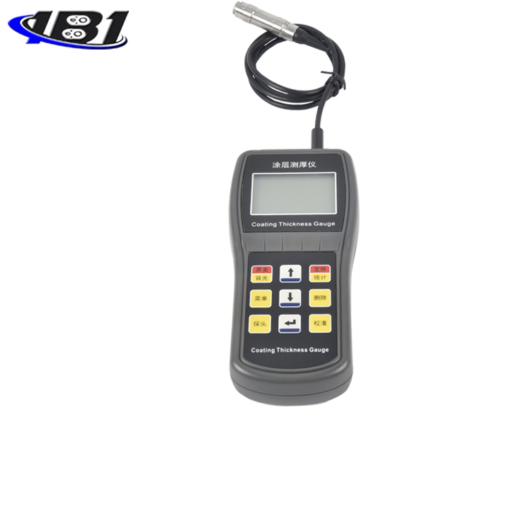

This instrument is a portable coating thickness gauge with magnetic and eddy current integration. It can quickly and accurately measure the thickness of coatings and coatings without damage. It can be used in the laboratory and engineering field. This instrument can be widely used in manufacturing, metal processing industry, chemical industry, commodity inspection and other detection fields, and is an essential instrument for material protection professionals.
This instrument meets the following standards:
GB / T 4956─1985 Non-magnetic coating thickness measurement on magnetic metal substrate Magnetic method
GB / T 4957─1985 Thickness measurement of non-conductive cover on non-magnetic metal substrate Eddy current method
JB / T 8393─1996 Magnetic and eddy current type coating thickness measuring instrument
JJG 889─95 \"Reluctance Thickness Gauge\"
JJG 818─93 \"Eddy current thickness gauge\"
Instrument Features:
Both magnetic and eddy current thickness measurement methods are used, which can measure the thickness of non-magnetic coatings on magnetic metal substrates and the thickness of non-conductive coatings on non-magnetic metal substrates.
Has two working modes: storage mode and normal mode.
Has two measurement modes: high-precision measurement mode can average multiple measurements and automatically filter suspicious data to ensure more accurate and stable measurement values; fast measurement mode can realize real-time scanning.
With temperature compensation function: China's leading real-time temperature compensation technology can automatically compensate for measurement errors caused by changes in ambient temperature and probe temperature, making the measurement more accurate.
Set five statistics: average (MEAN), maximum (MAX), minimum (MIN) test times (NO.), Standard deviation (S.DEV).
The instrument can be calibrated by zero-point calibration, single-point calibration, or two-point calibration, and the system error of the probe can be corrected by basic calibration and temperature coefficient calibration.
With storage function: up to 500 measured values can be stored.
With delete function: delete single suspicious data appearing in the measurement, and also delete all data in the storage area for new measurement.
Limits can be set: automatic alarming for measured values outside the limits.
With power and power indication function.
There are three types of shutdown methods: manual shutdown mode, timeout automatic shutdown mode and low-power automatic shutdown mode, and the automatic shutdown timeout can be set. The automatic shutdown is accompanied by backlight flashing and beeping prompts.
1.1 Measurement principle
This instrument uses two thickness measurement methods, magnetic and eddy current, to nondestructively measure the thickness of non-magnetic coatings (such as zinc, aluminum, chromium, copper, copper, Rubber, paint, etc.) and the thickness of non-conductive coatings on non-magnetic metal substrates (such as copper, aluminum, zinc, tin, etc.) (such as: rubber, paint, plastic, anodized films, etc.)
a) Magnetic method (F-type probe)
When the probe is in contact with the cover layer, the probe and the magnetic metal substrate form a closed magnetic circuit. Due to the presence of the non-magnetic cover layer, the magnetic resistance of the magnetic circuit changes. The thickness of the cover layer can be derived by measuring the change.
b) Eddy current method (N-type probe)
An high-frequency alternating current is used to generate an electromagnetic field in the coil. When the probe is in contact with the cover, an eddy current is generated on the metal substrate and a feedback effect is generated on the coil in the probe. The cover can be derived by measuring the magnitude of the feedback thickness of.
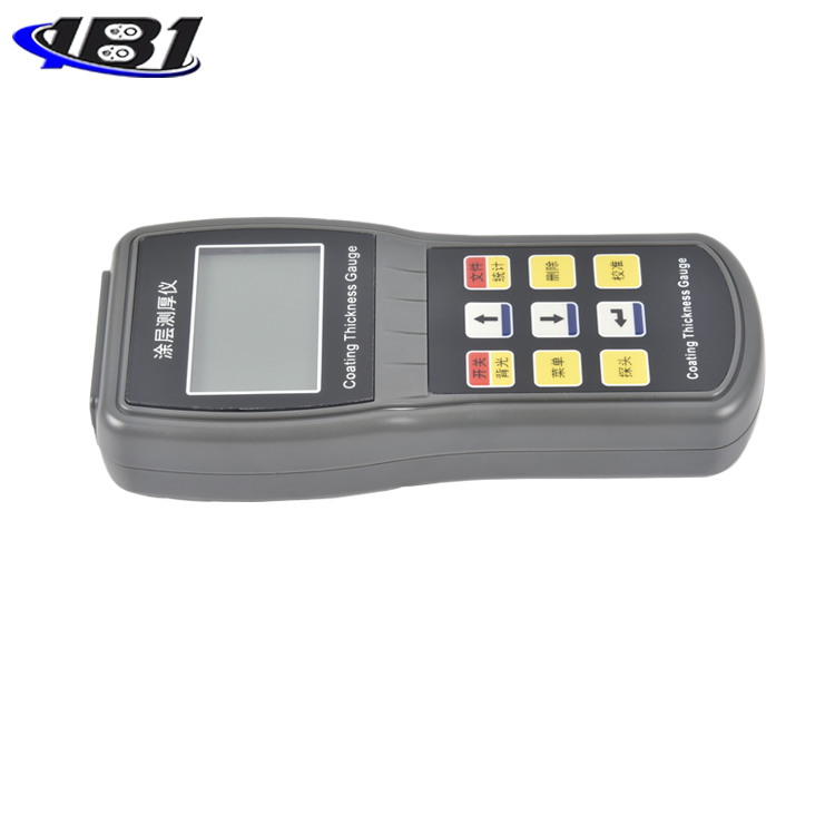
1.2 Instrument Introduction
|
Switch / Backlight |
|
|
|
Documents / Statistics |
|
|
Delete key |
|
menu |
|
|
Calibration key |
|
|
Enter |
|
|
Move up |
|
|
Move down |
|
|
Probe switch key |
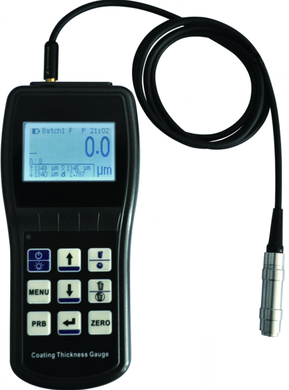
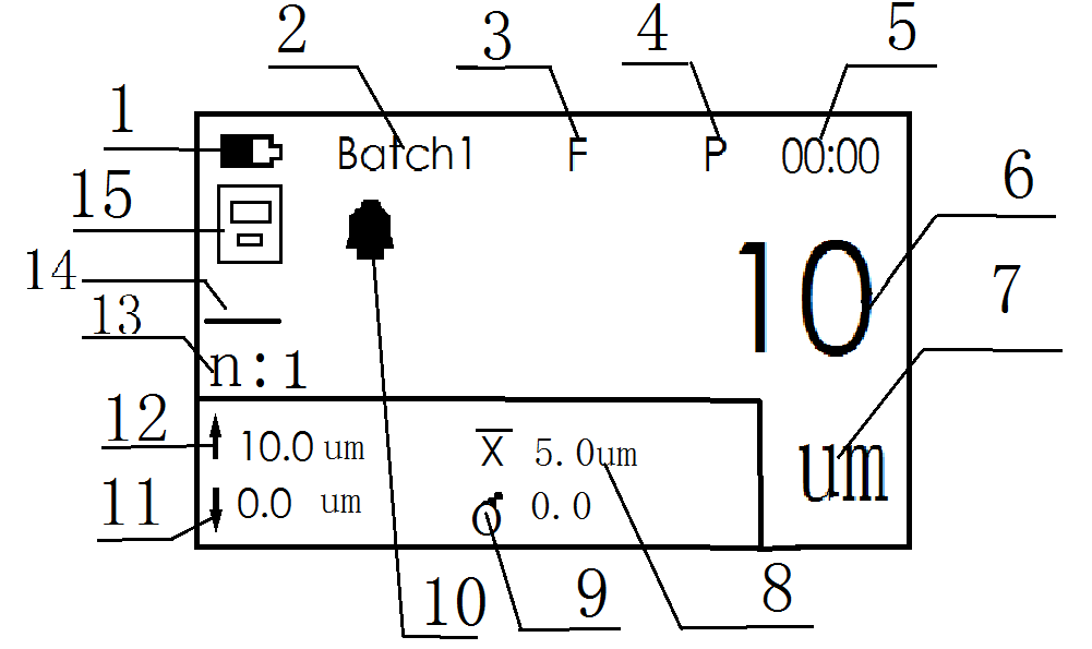
Figure 4 LCD display diagram
1.3 Technical parameters
1.3.1 Measurement range and measurement error (see Appendix 2)
1.3.2 Use environment
Temperature: 0 ℃ ~ 40 ℃
Humidity: 20% RH ~ 90% RH
No strong magnetic field environment
1.3.3 Power
Three AA alkaline batteries (1.5V)
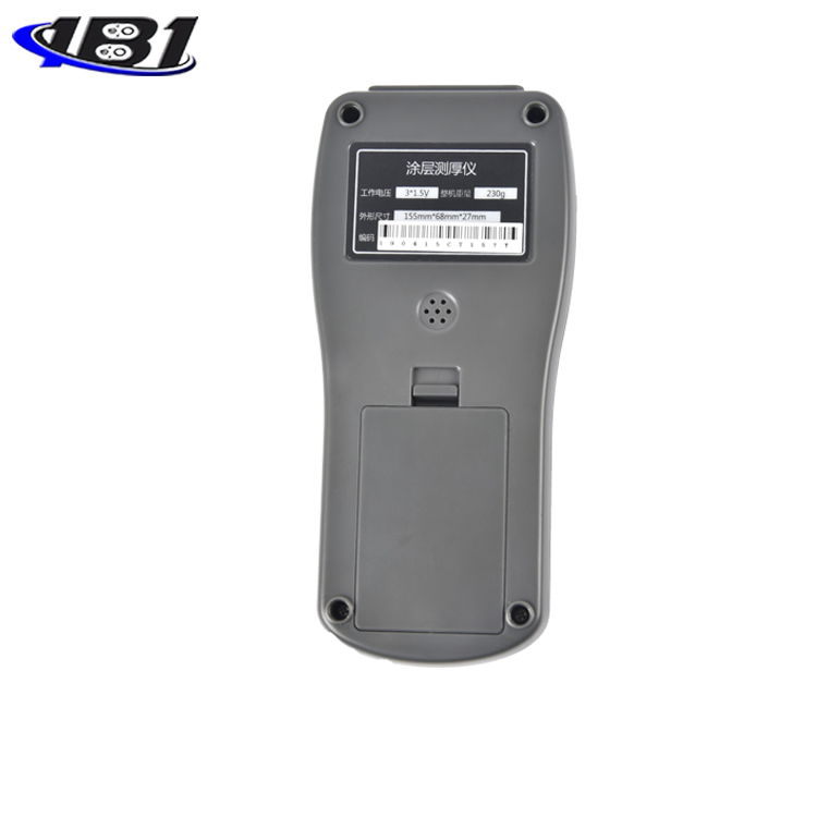
1.3.4 Overall dimensions and weight
Dimensions: 155mm × 68mm × 27mm
Weight: about 230g
Before using the instrument, please read Chapter 3 (Calibration of the Instrument) and Chapter 4 (Factors Affecting Measurement Accuracy) carefully.
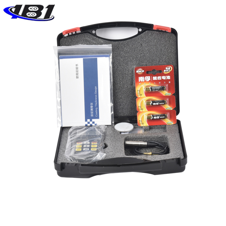
2.1 Installation and removal of the probe
2.1.1Probe installation
Before using the instrument, the probe should be correctly inserted into the probe slot above the instrument.
This instrument uses an audio plug to shield external interference signals for better insertion and removal.
2.1.2 Disassembly of the probe
After using the instrument, the probe should be removed and stored properly.
2.2 Basic measurement procedures
a) Prepare the part to be tested (see Chapter 4).
b) Place the probe in the open space, press the key, and switch on.
c) Check the battery level indicator. If the battery level is too low, replace the battery immediately.
d) Check the probe type. If the probe type indicator at the bottom of the screen does not match the actual probe type.
e) Whether it is necessary to calibrate the instrument, and if necessary, select an appropriate calibration method (see Chapter 3).
f) Shut down: Press and hold the key to shut down immediately; without any operation, the instrument will automatically shut down after about 2 to 3 minutes. The automatic shutdown wait time can be set. For details, see 2.4.2 Function Setting Procedure.
Explanation:
1) Try to use a base of the same material as the part to be tested for zero point calibration.
2) When the high-precision measurement mode is turned off, if the probe does not contact the measured object quickly and vertically, an unreliable measurement result may be obtained. Therefore, it is recommended to use continuous measurement in this case. Read again.
3) If the probe is not placed stably during the measurement, an unreliable measurement result may be obtained.
4) After saving multiple measured values, five statistics are displayed in real time in the test interface, namely: average (X), standard deviation (), number of measurements (N.), maximum measured value (↑), minimum measured value (↓).
2.3 Various functions and operation methods
This section details the various functions of the machine and how to operate it.
2.3.1 Probe selection (Auto ⇔F⇔N)
The following steps make probe selection:
a) On the main interface, the instrument will automatically identify the probe type and the\"\" F\"\" or\"\" N\"\" label appears.
The probe type is displayed in the probe type indication area at the top of the screen. \"F \" corresponds to the F-type probe and \"N \" corresponds to the N-type probe. If no probe is inserted in the automatic recognition mode, this display area No logo is displayed.
In some measurement environments, the external magnetic field interference is large, and the automatic recognition function of the instrument may not correctly identify the probe type. You can directly select the probe type by selecting \"F \" or \"N \" mode.
2.3.2 Measurement mode setting
In order to improve the measurement accuracy and stability, the instrument provides two working modes: high-precision measurement mode and fast measurement mode.
Press the key in the main interface to switch between the high-precision measurement mode and the fast measurement mode. When the high-precision measurement indicator \"P \" is displayed at the lower right of the screen, it indicates that the high-precision measurement mode has been entered. When the indicator disappears or appears \"Q \" indicates that the high-precision measurement mode has been exited. \"P \" means Precise Mode is high precision, Q means Quick Mode is fast mode.
In the fast measurement mode, it can be used with \"continuous measurement \" to realize real-time scanning measurement results for recording and data analysis in the view statistics interface.
In the high-precision measurement mode, the instrument will screen and average the results of multiple measurements, and automatically filter suspicious data with large deviations to ensure more accurate and stable measurement results. The reading time in this mode becomes longer about 2 ~ 3 seconds.
The following parameters can be used to set the high-precision measurement mode:
Setting the measurement accuracy: Setting the accuracy standard in the high-precision mode is divided into high, middle, and low. The higher the accuracy, the slower the measurement speed.
2.3.3 Measurement method (single measurement ⇔ continuous measurement)
You can use one of two measurement methods:
Single measurement: Each time the probe touches the DUT, a measurement result is displayed with a beep.
Continuous measurement: Continuous measurement without lifting the probe. When the high-precision mode is on, a new measurement result is displayed after each beep. When the high-precision mode is off, the measurement result is displayed in real time and only the first measurement result is accompanied by the beep.
For the conversion methods of the two methods, see 2.4.1 System Setting Procedure.
2.3.4 Storage method
Measurements can be made in one of two ways:
Storage method: It is used to store the user's measurement data. When the storage mode in the system setting is on, the storage interface displays a storage mark. Each measurement data will be recorded and counted.
Storage method: This method is convenient for users to record the tested data in batches. The measurement results will be automatically saved and participate in statistical calculations. Each group can store up to 100 values, for a total of five groups, and can store 500 values. When each group is filled with 100 values, the screen will display\"Memory Full\", and measurement can still be performed at this time, but the measured values will only be saved for the last 100 data and the earliest data will be lost in the update list.
Two conversion methods:
a) Press the key in the main interface to enter the main menu.
b) Press the key to switch to the storage mode in the system settings. Press the key to open the main interface and the storage icon will appear.
2.3.5 Set the current file
You can set the file of the currently stored data by the following methods:
a) Press in the main interface Press the key to cycle through the files Batch1 ~ Batch5 until the corresponding folder is selected.
Instructions: PressThe key is to switch the folder. Press and hold to enter the data view statistics page.
2.3.6 View / Delete Measurement Data
2.3.6.1 Viewing Measurement Data
You can view or delete the saved test data by the following steps:
a) Press and hold on the main interfacePress to enter the data view interface.
b) Press or key to view each measurement data, and Key to delete a certain measurement data.
c) Press to return.
2.3.6.2 Delete measurement data
Enter the function setting interface as described in 2.42 steps a ~ b. Press the or key to select \"Delete files \" or \"Delete all data \", and then press the key to enter the delete confirmation screen. Confirm the delete key and cancel the delete key. \"Delete file\" just deletes the data in the current file, while \"Delete all data \" deletes all five groups of data.
Press in the view statistics interfaceKey will delete the selected data, long press on the main interface and statistics interfaceThe key will delete the entire file. Pressing the delete key in the main interface will delete the most recent measurement data in turn.
2.3.7 System time setting
Setting the system time can correct the instrument's own time.
a) For the parameter setting method, please refer to 2.4.2 Function Setting Procedure to enter the system time setting. Press the key to select the time option Date Time and then press the or key to change the setting.
2.3.8 Standby time setting
After the standby time is set, the screen backlight flickers and the buzzer prompts when the instrument idle time reaches the standby time, and the instrument automatically turns off after the screen backlight flashes 6 times. While the screen backlight is flashing, press any key or take a measurement, and the instrument will exit the automatic shutdown state.
2.3.9 Notes on measurements and errors
If proper calibration has been performed, all measured values will remain within a certain error range (see Table 2).
From a statistical point of view, one reading is unreliable. Therefore, any displayed measurement value is the average of multiple\"invisible\" measurements. These measurements are made by the probe and the instrument in a fraction of a second.
In order to make the measurement more accurate, a statistical program can be used to measure multiple times at one point, and the measurement value with larger error can be deleted immediately after the measurement.
When using high-precision measurement mode, the instrument will screen and average the results of multiple measurements, and automatically filter suspicious data with large deviations to ensure more accurate and stable measurement data.
The final coating thickness is: CH = M + S + δ
among them:
CH coating thickness M average of multiple measurements
S standard deviation δ instrument allowable error
2.4 System Settings and Function Settings
Other parameters of the instrument can be modified through system settings or function settings. The system setting can set the language, unit, accuracy, measurement mode, alarm mode, buzzer and storage mode. Function settings can be used to restore default settings, delete all data, set contrast, set standby time, set system time, and version information.
2.4.1System setup steps
b) Press in the main interface to enter the main menu interface.
c) Press the or key to select the \"System Settings \" menu item, and then press the key to enter the system setting interface.
d) Press or to select the item, and then press to change the setting.
e) After the setting is completed, press the key to return.
a) Press in the main interface to enter the main menu interface.
b) Press the or key to select the \"Function Setting \" menu item, and then press the key to enter the function setting interface.
c) Press the or key to select the item, and then press the key to enter the setting.
d) Press the or key to set the parameter, then press the key to confirm and press the key to exit.
2.5 Measurements on sandblasted surfaces
The characteristics of the blasted surface cause the measurement value to be greatly distorted, and its coating thickness can be roughly determined by the surface method:
a) Calibrate on a smooth surface with the same radius of curvature as the substrate using the two-point calibration in 3.3.2 or the zero-point calibration method in 3.3.1.
b) Multiple measurements were performed on the uncoated surface subjected to the same blast treatment to obtain the average value Mo.
c) Perform multiple measurements on the coated surface to obtain the average Mm.
d) (Mm—Mo) ± S is the thickness of the cover layer.
Among them, S (standard deviation) is the larger of SMm and SMo.
3Calibration of the instrument
To make the measurement accurate, the instrument should be calibrated at the measurement location.
3.1 Calibration standards (including foil and substrate)
A foil of known thickness or a sample of known cover thickness can be used as a calibration standard, referred to as a standard.
a) Calibration foil
For magnetic methods,\"foil\" means non-magnetic metal or non-metal foil or gasket. For the eddy current method, plastic foil is usually used. \"Foil \" facilitates calibration on curved surfaces and is more suitable than standard films with overlays.
b) Covered standard film
As the standard sheet, a cover layer of known thickness, uniform and firmly bonded to the substrate is used. For magnetic methods, the cover is non-magnetic. For the eddy current method, the cover is non-conductive.
3.2 Substrate
a) For the magnetic method, the magnetic properties and surface roughness of the base metal of the standard sheet should be similar to those of the base metal of the part to be tested. For the eddy current method, the electrical properties of the standard substrate metal should be similar to the electrical properties of the substrate metal to be tested.
In order to verify the applicability of the standard film, the base metal of the standard film can be compared with the readings measured on the base metal of the piece to be tested.
b) If the thickness of the metal substrate of the part to be tested does not exceed the critical thickness specified in Table 2, the following two methods can be used for calibration:
i. Calibrate on a metal standard with the same thickness as the metal base of the part to be tested.
ii. Use a metal backing standard or test piece of sufficient thickness and similar electrical properties, provided that there is no gap between the base metal and the backing metal. For specimens with coatings on both sides, the pad method cannot be used.
c) If the curvature of the covering layer to be measured has not been calibrated on a plane, the curvature of the standard sheet with the covering layer or the curvature of the base metal placed under the calibration foil shall be the same as the curvature of the specimen.
This instrument provides two calibration methods used in measurement: zero-point calibration and two-point calibration; and two calibration methods for probes: basic calibration and temperature coefficient calibration.
3.3.1Zero calibration
Zero point calibration must be performed again when measuring on different substrates. When the nature of the substrate used for calibration is significantly different from that of the substrate to be tested, the measurement value will be biased. Zero calibration can be performed using one of two methods:
1 Calibration on the substrate
a) Take a measurement on the substrate and the screen displays <×× μm>.
b) Press the key before lifting the probe, the screen is displayed, and the calibration is completed.
Repeat steps a and b to obtain more accurate calibration results and improve measurement accuracy.
2 Calibration on standard (single-point calibration)
a) Before measuring with a probe, press the key in the main interface to enter the\"Zero Calibration\" mode.
b) Perform a measurement on the standard film, and the screen displays <××× μm>.
c) After the probe is lifted, press the or key to correct the reading to reach the target value.
d) Press to confirm and the calibration is completed; or press to cancel the calibration; or press to clear the saved calibration result.
Repeat steps a to d to obtain more accurate calibration results and improve measurement accuracy.
After using the standard film for zero point calibration, a higher measurement accuracy will be obtained when measuring the thickness similar to that of the standard film.
When using a standard film for zero point calibration, the thickness of the standard film is preferably less than 200um. If the thickness of the standard film is too large, the measurement accuracy of the test piece with a small thickness will be reduced.
When a calibration substrate that is the same as or similar to the substrate of the part to be tested cannot be found, the standard calibration method can be used to perform a zero point calibration on a test piece of known thickness.
3.3.2 Basic calibration
When the following problems cause the measurement curve to deviate, the basic calibration needs to be performed again:
a) Change the probe
b) The probe tip is worn
c) After repair of the probe
d) special purpose
The basic operation method is as follows:
a) Press and hold the key until the basic calibration mode is entered.
b) Select the probe type with the key. When the mark \"F \" is displayed at the top right of the screen, it means that the F-type magnetic probe will be basically calibrated. When the mark \"N \" is displayed at the top right of the screen, it will be N-type non-magnetic. The probe is basically calibrated.
c) INFINITY: Insert the probe, keep the probe away from the substrate, and press the key to confirm after the reading in the center of the screen is stable.
d) Calibration Zero (ZERO): Hold the probe close to the base, and press the key to confirm after the reading in the center of the screen is stable.
e) Using standard films, sequentially calibrate 5 ~ 10 thickness calibration points in order of increasing thickness:
i. Adjust the thickness value displayed at the top of the screen with the or key to make it the same thickness as the calibration test piece.
ii. Measure the calibration test piece, and press the button to confirm after the reading in the center of the screen is stable.
f) After all the calibration points are measured, the information of each calibration point will be displayed on the screen in sequence, and the\"\" PASS\"\" or\"\" FAIL\"\" marks will be displayed at the bottom of the screen to indicate the success or failure of the calibration. , You can press the key to enter the main interface, or pressPress the key to save the calibration result as the default setting. After saving as the default setting, the calibration information will be automatically read when using the restore default function.
note:
The calibration thickness must be gradually changed from small to large. When the calibration thickness or calibration value is abnormal, the calibration
Failure, \"FAIL \" is displayed at the bottom of the screen, the instrument still retains the previous calibration results
3.4 Explanation of influencing factors
a) Base metal magnetic
The thickness measurement by the magnetic method is affected by the magnetic change of the base metal (in practical applications, the magnetic change of low-carbon steel can be considered to be slight). Calibrate the instrument with a standard film; you can also use the test specimen to be coated for calibration.
b) Electrical properties of base metal
The conductivity of the base metal has an influence on the measurement, and the conductivity of the base metal is related to its material composition and heat treatment method. The instrument should be calibrated with a standard sheet with the same properties as the base metal of the test piece.
c) Base metal thickness
Each instrument has a critical thickness of the base metal. Above this thickness, the measurement is not affected by the thickness of the base metal. The critical thickness values of this instrument are shown in Table 2.
d) Edge effect
This instrument is sensitive to sudden changes in the surface shape of the test piece. It is not reliable to measure near the edge or inner corner of the test piece.
e) curvature
The curvature of the test piece has an effect on the measurement, and this effect always increases significantly as the radius of curvature decreases, so measurement on the surface of a curved test piece is not reliable.
f) Deformation of the test piece
The touch probe deforms the soft cover test pieces, and reliable data cannot be measured on these test pieces.
g) Surface roughness
The surface roughness of the base metal and the cover has an influence on the measurement. As the degree of roughness increases, the effect increases. Rough surfaces can cause systematic and occasional errors. Each measurement should increase the number of measurements at different locations to overcome this occasional error. If the base metal is rough, you must also take a few positions on the uncoated substrate with a similar roughness to perform zero calibration on the instrument or remove the cover with a solution that does not corrode the base metal, and then perform a zero calibration on the instrument .
h) Magnetic field
The strong magnetic fields generated by various electrical equipment around it will seriously interfere with the thickness measurement of the magnetic method.
i) Attached substances
This instrument is sensitive to those adherent substances that prevent the probe from coming into close contact with the surface of the cover. Therefore, the adherent substances must be removed to ensure that the probe of the instrument is in direct contact with the surface of the test piece.
j) Probe pressure
The pressure exerted by the stylus on the test piece will affect the measured reading, so keep the pressure constant.
k) Probe orientation
The placement of the probe has an influence on the measurement, and the probe should be kept perpendicular to the surface of the sample during the measurement.
3.5 Regulations to be followed when using the instrument
a) Base metal characteristics
For the magnetic method, the magnetic and surface roughness of the calibration base metal should be similar to that of the test sample base metal. For the eddy current method, the electrical properties of the calibration base metal should be similar to those of the test piece base metal.
b) Base metal thickness
Check whether the thickness of the base metal exceeds the critical thickness. If not, use one of the methods in 3.3 for calibration.
c) edge effects
Measurements should not be made close to sudden changes in the test piece, such as edges, holes, and inner corners.
d) Curvature
It shall not be measured on the curved surface of the test piece.
e) Number of readings
Usually because the instrument's readings are not exactly the same, several readings must be taken in each measurement area. Local differences in the thickness of the cover also require multiple measurements in any given area, especially when the surface is roughed.
f) Surface cleanliness
Before measurement, remove any attached substances on the surface, such as dust, corrosion, etc., but do not remove any covering materials.
4.1 Environmental requirements
Strictly avoid collisions, heavy dust, humidity, strong magnetic fields, and oil pollution.
4.2 Replacing the battery
When the instrument power is too low, the battery should be replaced in a timely manner, as follows:
1) Press the button to shut down, open the battery compartment cover and remove the battery;
2) Put the charged No. 7 alkaline battery into the battery compartment (note the battery polarity), and close the battery compartment cover.
When the instrument is not in use for a long time, the battery should be removed to prevent battery leakage from corroding the instrument.
Table 1 Factors Affecting Measurement Precision (▲ indicates influence)
|
Influencing factors |
Magnetic method |
Eddy current method |
|
Base metal magnetic |
▲ |
|
|
Electrical properties of base metal |
▲ |
|
|
Base metal thickness |
▲ |
▲ |
|
Edge effect |
▲ |
▲ |
|
Curvature |
▲ |
▲ |
|
Deformation of the specimen |
▲ |
▲ |
|
Surface roughness |
▲ |
▲ |
|
magnetic field |
▲ |
|
|
Attachment |
▲ |
▲ |
|
Probe pressure |
▲ |
▲ |
|
Probe orientation |
▲ |
▲ |
Table 2Technical parameter table (H is the nominal thickness value)
|
Probe type |
F |
N |
|
|
working principle |
Magnetic induction |
vortex |
|
|
Measurement range (μm) |
0 ~ 1500 |
0 ~ 1500 |
|
|
Low resolution (μm) |
0.1 |
0.1 |
|
|
Indication |
Zero point calibration (μm) |
± (3% H + 1) |
± (3% H + 1) |
|
Two-point calibration (μm) |
± [(1 ~ 3)% H + 1] |
± [(1 ~ 3)% H + 1] |
|
|
Test Conditions |
Minimum curvature radius (mm) |
Convex 1.5 |
Convex 3 |
|
Minimum area diameter (mm) |
Φ7 |
Φ5 |
|
|
Critical thickness of substrate (mm) |
0.5 |
0.3 |
|
Table 3 Reference table for probe selection
|
Overlay Matrix |
Non-magnetic coatings such as organic materials (e.g. paint, lacquer, enamel, plastic and anodizing, etc.) |
Non-magnetic non-ferrous metal coatings (e.g. chromium, zinc, aluminum, copper, tin, silver, etc.) |
|
Magnetic metals such as iron and steel |
F probe Measuring range: 0 ~ 1500μm |
F probe Measuring range: 0 ~ 1500μm |
|
Non-ferrous metals such as copper, aluminum, brass, zinc, tin |
N-type probe Measuring range: 0 ~ 1500μm |
N-type probe (Only for chrome plating on copper) Measuring range: 0 ~ 40μm |
1. After the user purchases our products, please fill out the\"Warranty Registration Card\" carefully and affix the official seal of the user unit. Please send the\"Warranty Registration Card\" and a copy of the purchase invoice to the customer service department of the company, or you can entrust the sales unit to send it on behalf of the purchaser. When the procedure is incomplete, it can only be repaired without warranty.
2. Our company's products have quality failures (except non-warranty parts) within one year from the date of purchase. Please contact \"warranty card \" or a copy of the purchase invoice to contact the company's branch service stations for repairs. Product, replacement or return. During the warranty period, you cannot show the warranty card or a copy of the purchase invoice. The company calculates the warranty period based on the date of manufacture and the period is one year.
3. If the company's product that has exceeded the warranty period fails, maintenance stations around the country will be responsible for after-sales service and product maintenance, and will charge maintenance fees in accordance with the company's regulations.
4.\"Special configuration\" (special-shaped probes, special software, etc.) outside the company's final products are charged according to relevant standards.
5. Any product damage caused by the user disassembling and disassembling the company's products, improper transportation, storage or incorrect operation according to the \"Product Instruction Manual \", as well as altering the warranty card without permission, the company cannot guarantee it .