support hotline
0577-57572522
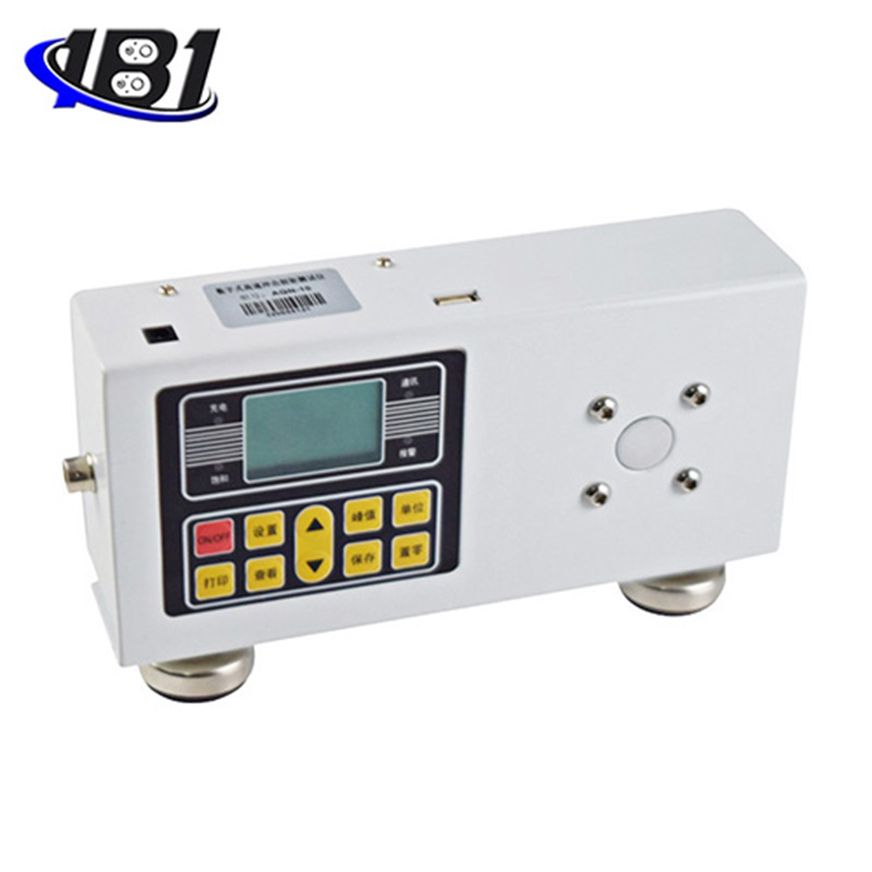
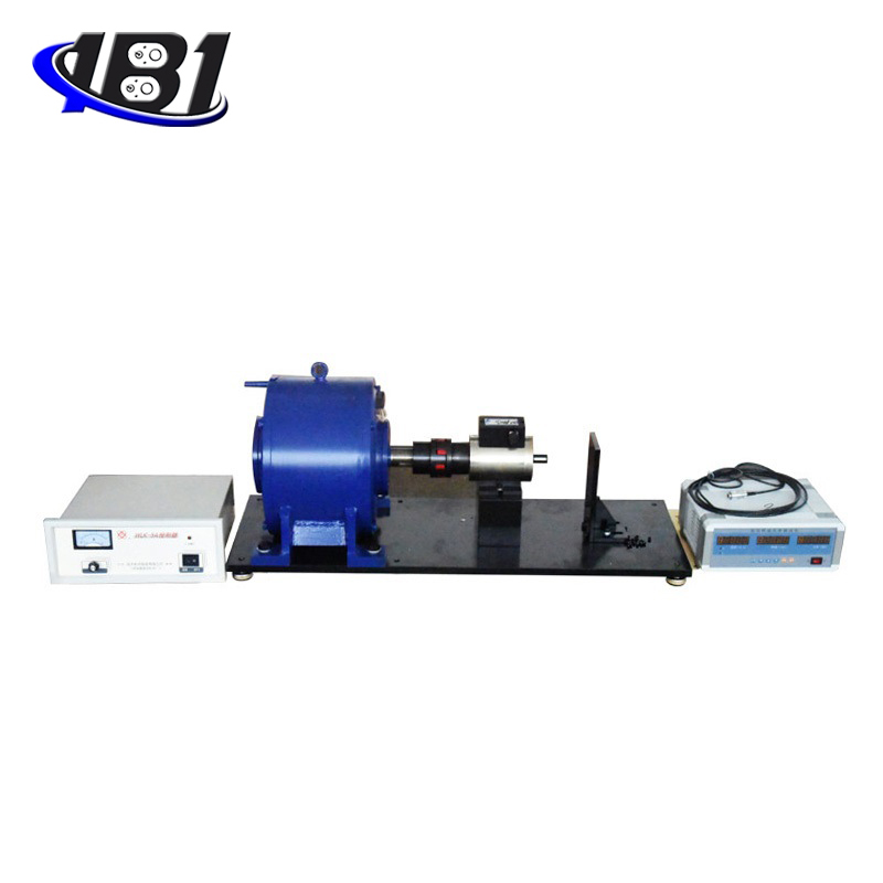
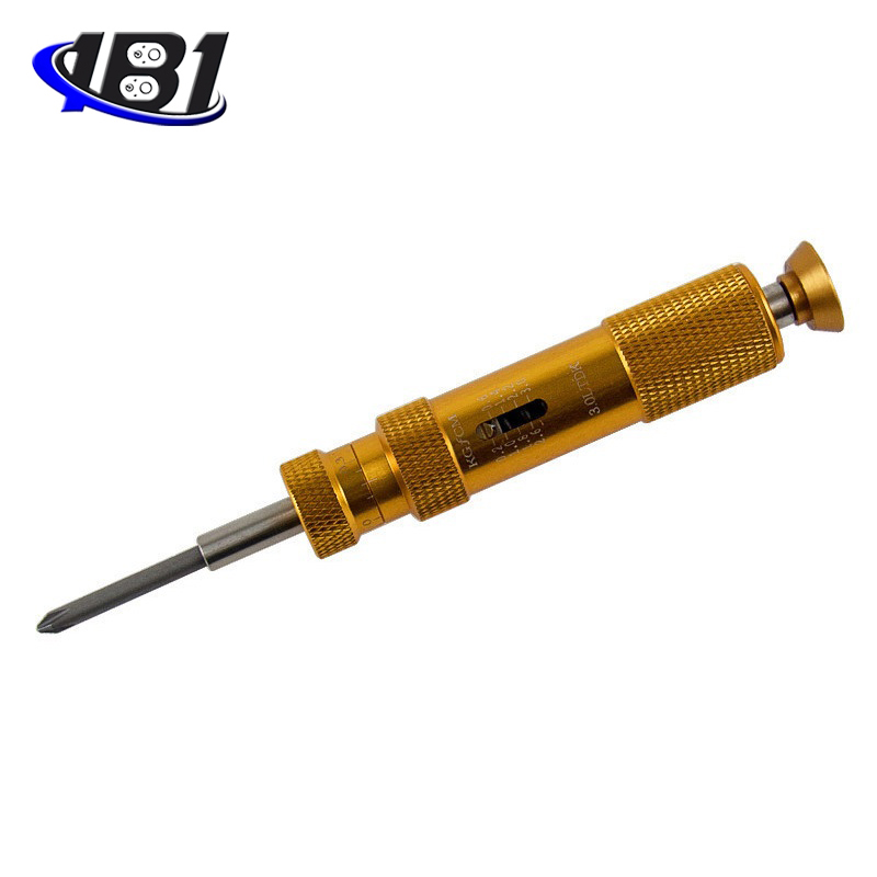
High speed impact torque tester is an intelligent multi-functional measuring instrument designed and manufactured for testing and testing various torques.It is mainly used for testing and correcting the torque of various electric pneumatic screwdrivers and torque spanners. Various products involve the test of tightening force and the torsion destructive test of parts.It has the characteristics of simple operation, high precision, full function and easy to carry. It is widely used in various electrical, light industry, machinery manufacturing, scientific research institutions and other industries.
|
model
index |
With printer |
EGN-1P |
EGN-2P |
EGN-3P |
EGN-5P |
EGN-10P |
EGN-20P |
|
Without printer class |
EGN-1 |
EGN-2 |
EGN-3 |
EGN-5 |
EGN-10 |
EGN-20 |
|
|
measuring range / Minute Degree value |
N · m |
1.0000 / |
2.0000 / 0.0001 |
3.0000 / 0.0001 |
5.0000 / 0.0001 |
10.000 / 0.001 |
20.000 / 0.001 |
|
Kg · cm |
10.210 / 0.001 |
20.421 / 0.001 |
30.631 / 0.001 |
51.052 / 0.001 |
102.10 / 0.01 |
204.21 / 0.01 |
|
|
Ib · in |
8.862 / 0.001 |
17.724 / 0.001 |
26.586 / 0.001 |
44.311 / 0.001 |
88.62 / 0.01 |
177.24 / 0.01 |
|
|
Precision |
± 1% |
||||||
|
Peak sampling frequency |
2000HZ |
||||||
|
Test speed |
≤15000rpm |
||||||
|
power supply |
8.4V 1.2VX7 Ni-MH battery pack |
||||||
|
Charging time |
4 to 6 hours |
||||||
|
Battery continuous use time |
About 10 hours |
||||||
|
Battery Life |
≥300 times |
||||||
|
size |
With printer: 230mm × 95mm × 180mm Without printer: 230mm × 70mm × 125mm |
||||||
|
Net Weight |
With printer: 5KG Without printer: 3KG |
||||||
|
Power Adapter |
Input: AC 220V 50HZ Output: DC 10V 300mA |
||||||
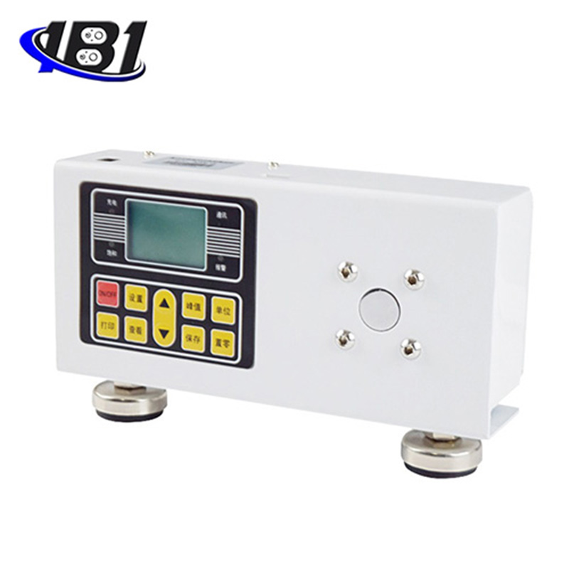
3、 Main features
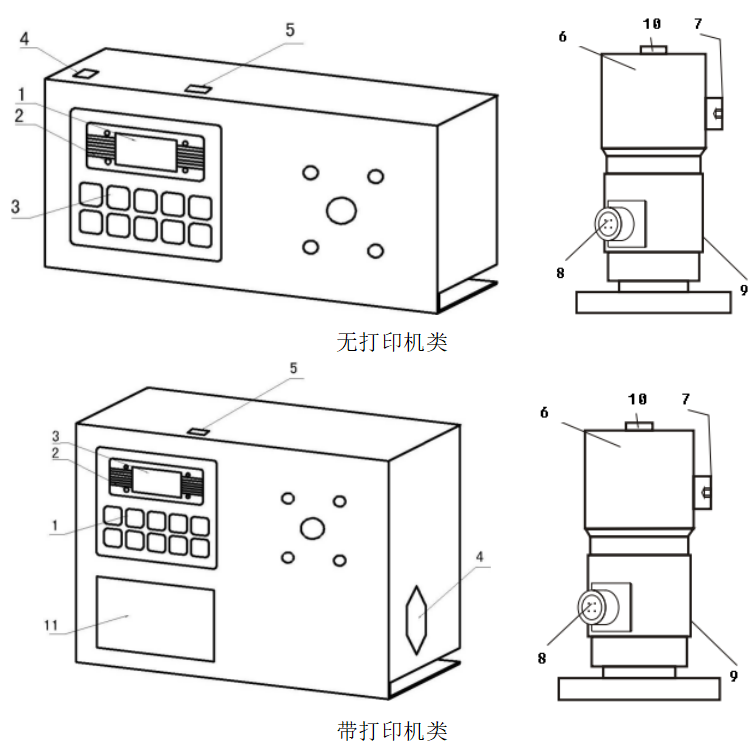
1. LCD window
a. Power on display

b. Main user interface display
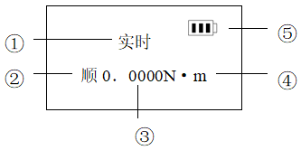
2. & nbsp; lights
3. Function keys
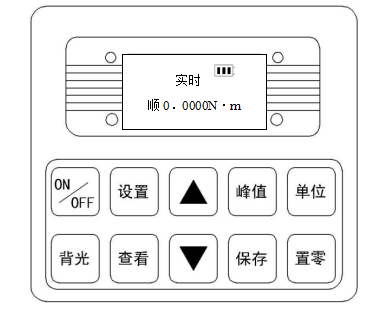
a. On / off key: power switch, power on and off.
b. "Print" key: it is used for the instrument equipped with printer. Press this key to print out the measurement data stored in the instrument (except for those without printing function).
c. "Setting" key: the user can enter the setting menu through this key in the measurement mode.
d. "View" key: in the measurement mode, you can view the stored measurement data through this key, and press it again to return to the measurement mode.
e. "+" key: in the user setting interface, press this key to modify the setting items up and down; in the parameter setting, press this key to modify the data in the current position; in the view interface, press this key to view the previous data.
f. "{" key: in the user setting interface, press this key to modify the setting item down; during parameter setting, press this key to move by bit to select the number of digits to be modified; in the view interface, press this key to view the next data.
g. "Peak value" key: used to switch three measurement modes: real-time, peak value and automatic peak value.
h. "Save" key: used to save the measured data.
i. "Unit" key: used to switch n · m, KGF · cm, IB · in three units.
j. "Zero" key:
① In real-time measurement, press this key to correct the zero point
② In peak and automatic peak, press this key to clear the peak value and return to zero point
③ When viewing the interface, press this key three times to delete all records
④ In the user setting interface, press this key to return to the previous interface without saving data.
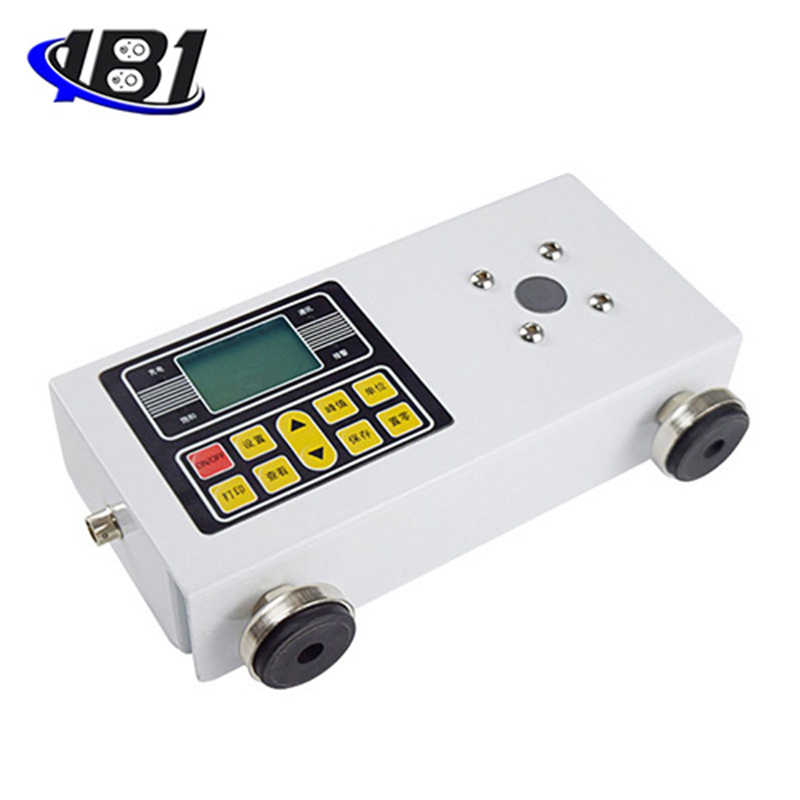
4. Power socket: used to connect with external power supply or charge.
5. Communication interface: USB interface output, used to connect computer.
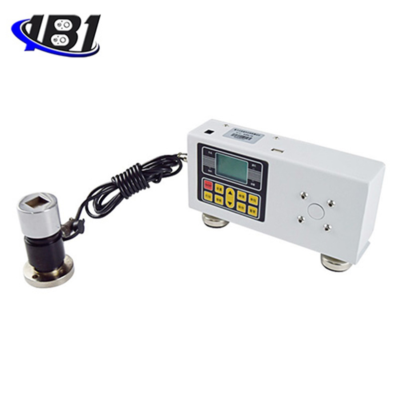
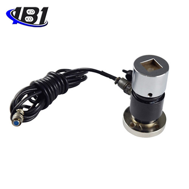
6. Test head: transfer torque load to sensor.
7. Cylindrical head screw: lock the test head.
8. Sensor cable interface
9. Torque sensor
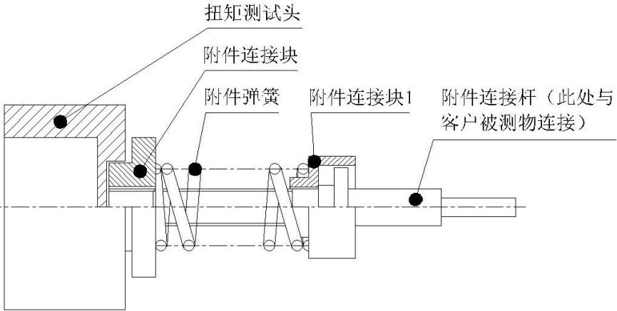
10. Connector: (to buffer)
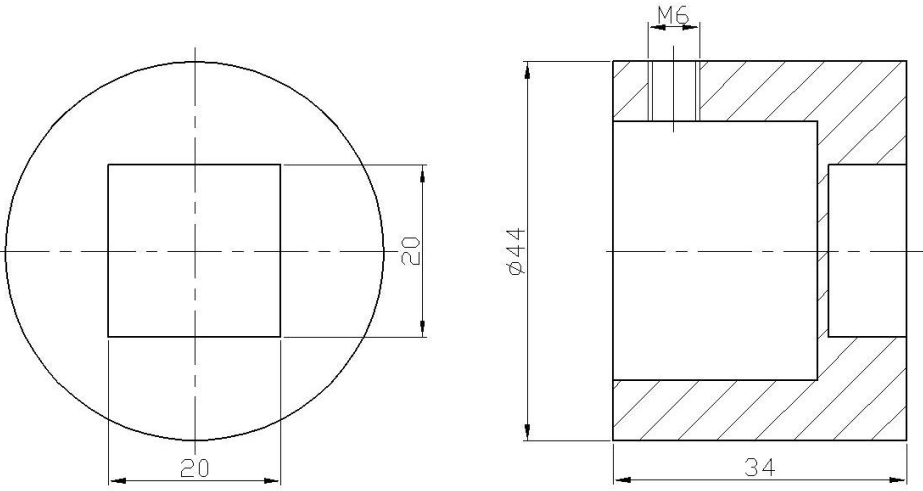
Test scope, installation (as shown in the figure below) and inspection of buffer
① , & nbsp; buffer test range
|
Model |
Buffer test range |
Remarks |
|
EGN-3、EGN-5、EGN-10、EGN-20 |
0.5-3N.m |
Use spring with wire diameter d = 3.5 |
|
EGN-1、EGN-2 |
0.15-0.6N.m |
Use spring with wire diameter d = 2.5 |
② Installation of buffer: select the bearing and spring according to the test requirements, and then rotate it in the counter clockwise direction to install the spring.
③ Inspection of buffer:
A. Check buffer before use. Dust, lack of grease and bending of shaft sleeve will affect the accuracy of torque test.
B. Check the buffer regularly. If the buffer is used repeatedly for a long time, the buffer will be worn and the accuracy of torque test will be affected. If there is wear, it needs to be replaced.
11. Printer: print out the measurement data stored in the instrument.
3. Under normal conditions, turn on the power switch and the displayed torque value is zero. If it is not zero, press the reset key to reset the torque value.
4. Before the test, the upper and lower limits, the minimum storage value, the minimum peak holding value, the automatic peak time, the automatic shutdown time, and the gravity acceleration should be set. The specific operation steps are as follows:
a. Press the "set" key for the first time in the user main interface to enter the user setting interface, and the display screen shows as follows:
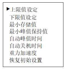
Select the setting item by up key or down key. When the user's setting item is selected, enter the parameter setting interface by pressing the setting key.
b. Parameter setting interface
In the user setting interface, press the "set" key to enter the parameter setting interface, and the display is as follows:
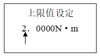
Description of setting parameters: (the above limit value is set as an example)
The data can be modified and shifted by "+" and "{" keys. At this time, press the "save" key to save the setting data, and the display interface will return to the user setting interface to set the next setting item.(if you press the "zero" key, you will return to the user setting interface without saving the modified data). When all the settings are set and saved, press the "on / off" key to turn off the machine, and then press the "on / off" key to start the machine, and enter the main user interface.The set data cannot exceed the maximum load value.
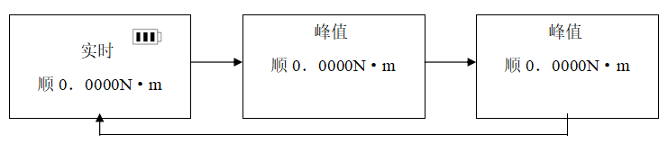
5. Before testing, the second choice is measurement mode
Real time measurement mode is displayed in the main user interface. When the "peak value" key is pressed for the first time to enter the peak value measurement mode, the "peak value" key is pressed for the second time to enter the automatic peak value measurement mode, and then (that is, the third time) the "peak value" key is pressed again to return to the real-time measurement mode and cycle in turn, as shown in the following figure:
6. Before the test, the second choice is the unit of measurement
In any measurement mode, press the "unit" key for the first time to enter the display of kg · cm unit from n · m unit, and press the "unit" key for the second time to enter IB · in unit display.
7. During the test, the measurement data can be saved by pressing the "save" key.
Note: during the test, when the measured value exceeds the upper limit value, the communication indicator will display red, and the buzzer will give an alarm; when the measured value is lower than the lower limit value, the communication indicator light will show green, and the buzzer will still give an alarm.When the measured value exceeds 120% of the maximum load, the sensor may be damaged.When the measured value exceeds 150% of the maximum load, it will definitely cause damage to the system.When the "serious overload" warning prompt appears, the instrument will automatically shut down, and the instrument will enter the automatic protection state. It is necessary to restart the machine. The display screen will display the warning prompt of "serious overload". Press the "setting" key to enter the user setting interface. Select the initial setting item through the "{" key, and then press the "setting" key. The display screen will display the password input prompt, and the password will be input by pressing "}"“It can be restored by pressing {"," peak value "," save ", & nbsp;"} ","} "," peak value "and" save "keys (please contact the manufacturer if unable to restore).
8. After the test, you can press the "view" key to view the saved data, and display the previous saved data or the next saved data through the "+" and "{" keys.
9. After using the torque tester, press the "on / off" key to turn off the power switch and put the tester back into the instrument box.
The instrument communicates with the host computer through USB.The communication protocol is MODBUS-RTU.The specific connection method between the instrument and the software is as follows:
1. Connect the instrument with the computer by direct connection, connect the instrument with USB male, and connect the RS-232 female with the computer.
2. Turn on the power supply of the instrument to make the instrument in the measurement interface.
3. Put the attached CD into the CD-ROM drive and open the serial port software path: CD-ROM drive\AutoTest.exe。
4. Click the "system" button at the bottom of the software window to pop up the "system settings" dialog box. Select the corresponding serial port with the computer from the communication port. The specific operation steps are as follows:
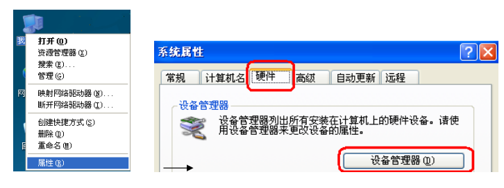
① Right click "my computer" and select "properties". In the pop-up "system properties" dialog box, select the "hardware" option bar, and then click the "device manager" button (as shown in the figure below)
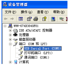
② In the pop-up "device manager" dialog box, view the serial port number of the sub item of the port item class (as shown in the figure below)
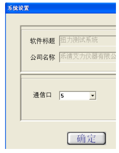
③ Return to the "system settings" dialog box pop up by the software, select the corresponding serial port number in the communication port (compared to "5"), and then press OK, as shown in the following figure:
④ Close the software and double-click againAutoTest.exeAfter that, you can check whether the serial port has been connected. There are many inspection methods: apply a point force on the sensor of the instrument, and check whether the torque value above the software window corresponds to the runout. If the torque value jumps, it means that it has been connected, otherwise, it is the opposite.
⑤ Click the "Settings" button at the bottom of the software window to pop up the "parameter setting" dialog box, and fill in the corresponding data according to the test needs.The specific parameter size is as shown in step 6-3-b.After filling in, press the "OK" button.After the setting is successful, the data displayed at the bottom of the software window will change accordingly.

⑥ First, make sure that the serial port is connected, and press the "start" button for synchronization test.
⑦ After the test, press the "stop" button and click "save" or "stop".Save will save the test curve into the software, stop it will be the opposite.
⑧ Software interface introduction:
a. There are torque value display area, time display area and test number number on the top.
b. On the left, there are upper limit line, lower limit line, indicator line, specification display, display curve, clear curve and export curve.
Upper limit line: when the box in front of the upper limit line is checked, the curve display window will display the horizontal line of the upper limit torque value.
Lower limit line: when the box in front of the lower limit line is checked, the curve display window will display the horizontal line of the lower limit torque value.
Indicator line: that is, the mouse is in a cross shape in the curve display window, and the torque value display area and time display area corresponding to the position of the cross mouse will change accordingly.
Specification display: as the name implies, it is the specification (model and range) of the display instrument.
Display curve: click this button to pop up the "select curve" dialog box, select the test items to be displayed, and then select the number of tests to be displayed.
Clear curve: only erase the currently displayed curve, not delete it from the software.
c. There are set, start, stop, report, system, help, delete and exit buttons below.
The setup, start, stop, and system buttons have been described earlier.
Report: click this button to jump out of the "curve data selection preview" dialog box. First select the size of sampling point frequency, then select the test items and test times to be displayed, and finally click the "EXECL" button.