support hotline
0577-57572522
Ⅰ. Instructions for use of the sensor
First, packing inspection
After unpacking, please carefully count the items listed in the \"Packing List\" first, confirm whether the items in the box are consistent with the \"Packing List\", check whether the items are damaged during transportation, and check the nameplate of the delivered product. Confirm that the product model, specifications and parameters are consistent with your order requirements. If you have any questions, please contact our company quickly.
Note: For special customized products, the items in the box are subject to those listed in \"Packing List\".
Box contents:
① Packing list ② Sensor ③ Aviation plug ④ Instruction manual ⑤ Certificate of conformity ⑥ Transmitter ⑦ Verification report
Second, the basic principle of torque measurement
The torque value of the sensor is measured using the principle of electrical strain measurement. When the strain axis is slightly deformed by the torque, the resistance value of the strain gauge attached to the strain axis changes accordingly. We will use a strain gauge with the same strain characteristics to form a measuring bridge. The change in strain resistance can be converted into a change in the voltage signal for measurement. The following is the main principle block diagram of torque measurement. Due to the non-contact coupling of energy and signal, the torque value (torque) measurement in the rotating state is perfectly solved.
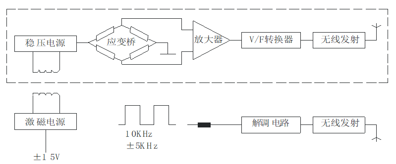
1. The power is sent after processing, and sent to the strain axis through the excitation power;
2. The stabilized voltage is changed from a stabilized power supply to each electronic device on the strain axis;
3. The slight deformation of the strain axis is converted into an electrical signal, which is converted into a frequency signal proportional to the torsional strain after voltage / frequency conversion. After the shaping by the mediation circuit, an FM square wave signal is output.
Third, the basic principle of speed measurement
Rotational speed measurement: Rotational speed measurement uses magnetic code disk method. Each magnetic code disk has 60 teeth. The shaft drives the magnetic code disk to generate 60 pulses every one rotation. Frequency measurement can be used for high-speed or medium-speed sampling. Method, low speed sampling can be used to measure the accurate rotation speed. The accuracy of this sensor can reach ± 0.1% ~ ± 0.5% (F · S). Because the sensor output is a frequency signal, it can be directly sent to a computer for data processing without AD conversion.
The speed measurement method of this sensor uses the built-in speed measurement. When ordering, the user must indicate whether to monitor the speed signal.
Product features:
1. The square wave amplitude of the signal output waveform can be selected from 5V / 12V.
2. You can enter the working state within 5 minutes after starting the machine, without preheating.
3. High detection accuracy, good stability and strong anti-interference.
4. Continuously measure forward and reverse torque without repeated zero adjustment.
5, small size, light weight, easy to install.
6. The sensor can be used independently of the secondary meter. As long as the power of ± 15V (200mA) is provided according to the pin number of the socket, it can output an equal square wave or pulse wave frequency signal whose impedance is proportional to the torque.
V. Main performance and electrical indicators:
|
Torque accuracy |
< ± 0.5% F · S, < ± 0.3% F · S, < ± 0.1% F · S (optional) |
|
Frequency response |
100μs |
|
Non-linear |
< ± 0.2% F · S |
|
Repeatability |
< ± 0.1% F · S |
|
Return difference |
0.1% F · S |
|
Zero drift |
< 0.2% F · S |
|
Zero temperature drift |
< 0.2% F · S / 10 ℃ |
|
Output impedance |
350Ω ± 1Ω, 700Ω ± 3Ω, 1000Ω ± 5Ω (optional) |
|
Insulation resistance |
> 500MΩ |
|
Static overload |
120% 150% 200% (optional) |
|
Operating temperature |
-10 ~ 50 ℃ |
|
Storage temperature |
-20 to 70 ° C |
|
voltage |
± 15V ± 5% |
|
Total current consumption |
< 200mA |
|
Frequency signal output |
5KHZ15KHZ |
|
Rated torque |
10KHZ ± 5kHZ (both positive and negative measured values) |
|
Signal duty cycle |
(50 ± 10) |
Note: * Determine positive and reverse torque: Fix one end of the shaft and apply torque clockwise at the other end to determine positive torque; otherwise, negative torque.
Note: The installation of the sensor must be performed by a professional mechanical installer
Installation of GB-DTS sensor
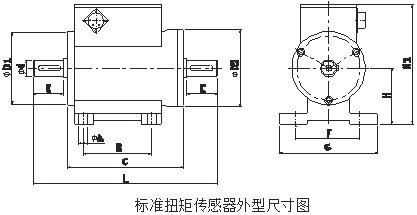
|
specification (N.M) |
Φ d |
ΦD2 |
A |
B |
C |
E |
F |
G |
H |
H1 |
L |
键 b * h * l * n |
|
0-100 |
18 |
78 |
8 |
72 |
122 |
31 |
61 |
100 |
54 |
112 |
188 |
6x6x25x1 |
|
200 |
28 |
92 |
8 |
72 |
123 |
41 |
61 |
100 |
60 |
125 |
209 |
8x7x35x1 |
|
500 |
38 |
96 |
8 |
72 |
124 |
55 |
61 |
100 |
65 |
135 |
238 |
10x8x50x2 |
|
1K-2K |
48 |
106 |
8 |
69 |
126 |
70 |
78 |
120 |
68 |
144 |
270 |
14x9x65x2 |
|
5K |
75 |
144 |
13 |
69 |
132 |
105 |
85 |
120 |
90 |
185 |
347 |
20x14x95x2 |
|
10K |
98 |
158 |
13 |
80 |
144 |
120 |
110 |
160 |
110 |
214 |
389 |
28x16x115x2 |
Note: Above 10KN · m need to be customized.
Seven, installation diagram
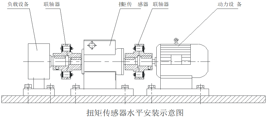
Installation method
1. The shaft diameter and center height of the measuring sensor are to be installed.
2. Use two sets of couplings to install the sensor between the power equipment and the load.
3. Adjust the center height and coaxiality of the power equipment, load, and sensor separately, and then fix them and fasten them reliably. No looseness is allowed.
4. Rigid or elastic couplings can be selected. In the case of large vibration or coaxiality greater than 0.05mm, it is recommended to use elastic couplings.
5. The mounting base should have a certain strength.
6, the coupling should be close to the shaft shoulders at both ends of the sensor.
pay attention
◆ Environmental requirements for installation:
Temperature: -10 ℃ ~ 60 ℃
Humidity: <90% RH
No flammable and explosive materials
◆ Do not directly hit or hit the sensor during installation.
◆ Do not operate with power on during installation.
◆ This sensor is non-waterproof and explosion-proof. Please pay attention when using it.
◆ Avoid strong interference and ensure the normal operation of the instrument.
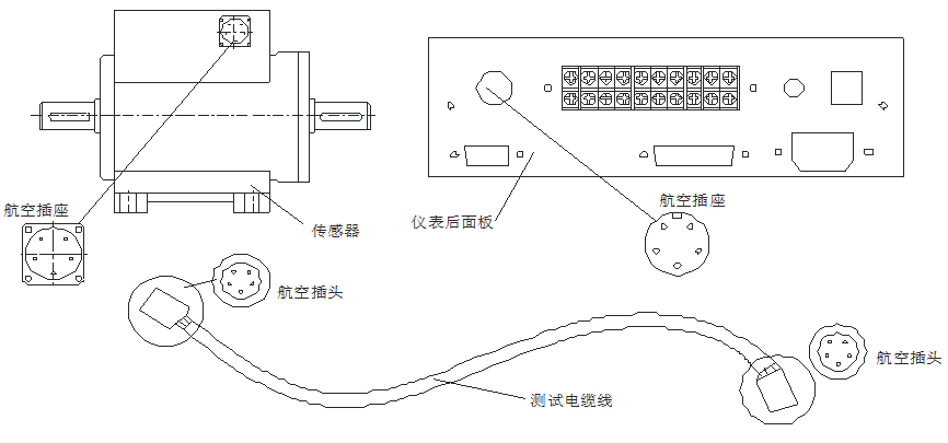
Nine, sensor and instrument connection
1. Make sure that the power of the instrument is turned off.
2. Connect the test cable (as per attached picture).
3. Turn on the meter power switch to work.
Note: Please read the digital measuring instrument section for meter usage. Figures:
pay attention
◆ To avoid electric shock, a three-core power cord should be connected to a three-wire power outlet for power supply.
The center ground of the power socket must be reliably grounded.
◆ The online test cable should be properly fixed to prevent the rotating system from twisting it.
◆ The shielded wire contact at the aviation plug of the test cable should not be removed at will.
◆ The aviation plug of the test cable and the aviation socket of the sensor and instrument should be tightened reliably.
How to use when the secondary meter is not selected
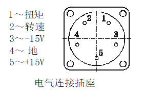
When the sensor is powered by an external power supply, it must be a stable DC voltage that meets the current of 300mA and the voltage of ± 15v.
See the lead definition of the aviation socket for specific connections:
Ten, care and maintenance
Due to environmental temperature, humidity, dust, vibration and other similar effects, as well as aging and abrasion of the components inside the sensor, potential sensor failures will occur. Therefore, it is necessary to implement daily and regular maintenance.
Eleven, routine maintenance, maintenance
The sensor must operate in the environment specified in the instructions. In addition, some unexpected situations may occur during operation. Users should perform routine maintenance according to the following inspections to maintain a good operating environment, and early detection of abnormal causes is the way to maintain long-term sensor operation.
Before maintenance, please confirm that the power supply of the power supply and sensor has been cut off.
Twelve, check the operating status
1. Check whether the temperature and humidity of the operating environment meet the requirements in the instructions.
2. Check the vibration of the sensor system and the temperature and noise of the bearing parts at both ends of the housing. Smooth operation, suitable humidity, no strange noise.
3. Check whether the system's fasteners are loose.
Thirteen, check the electrical parameters of the operating system
Check whether the power system voltage and the sensor supply voltage in the running system are within the rated value.
14. Regular maintenance and maintenance
1. According to the use requirements and environment, the user can perform a periodic inspection of the sensor for half a year or one year.
2. In addition to the routine maintenance and maintenance, the inspection items should also be cleaned and lubricated with bearings.
3. Only trained personnel can perform maintenance and device replacement after disassembling parts.
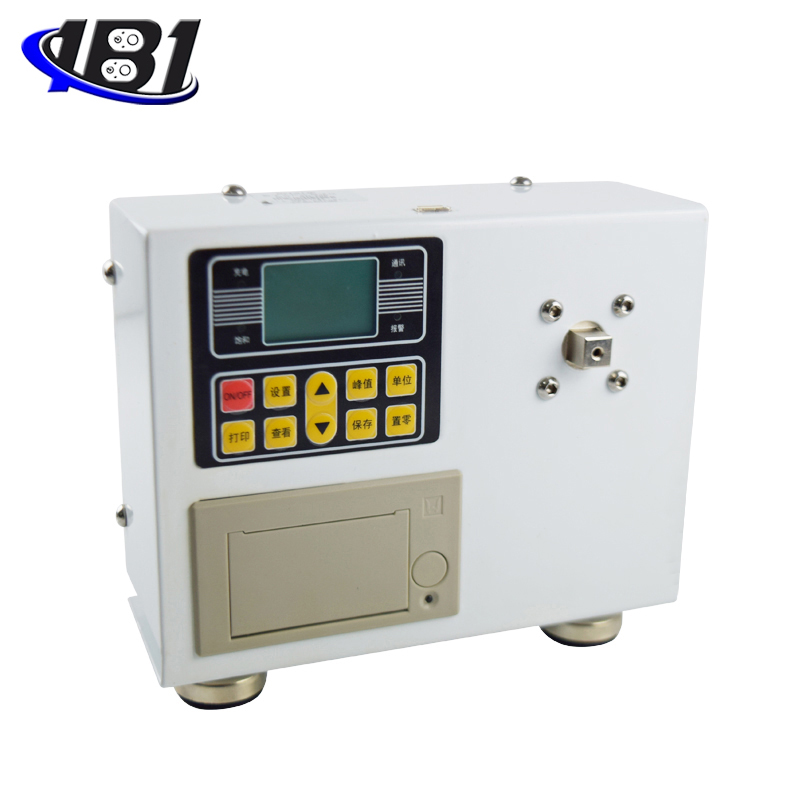
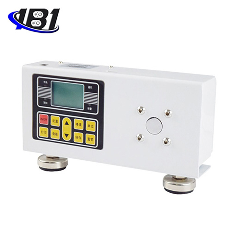
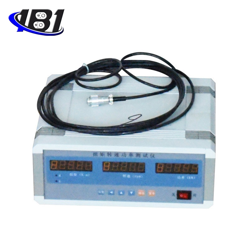
Ⅱ 、 Instructions for using the meter
15. Technical Specifications
1. Basic technical specifications
● K-type small desktop, size: 216 × 90 × 90 × 280.
● Instrument power: 220VAC.
● Display range:
Torque display: -19999 ~ 19999, the decimal point position can be set.
Speed display: -1999 ~ 4500, decimal point position can be set.
Power display: 0 ~ 9999, decimal point is adjusted automatically.
● Pulse input signal: Proximity switches for various NPN, PNP, OC gate outputs, rotary encoders.
● Counting frequency: Rotational speed pulse input 2Hz ~ 1.5KHz
Torque pulse input is 5KHz ~ 15KHz.
2.Option technical specifications
● Alarm output
◎ 2 alarm modes, selectable by setting, delayed alarm function.
◎ Relay output: contact capacity 220V AC, 3A.
● Transmission output
◎ Photoelectric isolation.
◎ 4mA ~ 20mA, 0mA ~ 10mA, 0mA ~ 20mA DC current output, selectable by setting.
◎ The load capacity is 600Ω.
◎ 1V ~ 5V, 1V ~ 5V DC voltage output, please specify when ordering.
◎ Output resolution: 1/4000, error is less than 0.2% F · S.
● Communication interface
◎ Photoelectric isolation.
◎ RS232, RS485 standards, please indicate when ordering.
◎ Instrument address 0 ~ 99 can be set
◎ Communication rate 2400, 4800, 9600, 19200 is selected by setting. The rate lower than 2400 should be specified when ordering.
● Printing interface and printing unit
◎ Built-in hardware clock, power failure does not affect travel time, automatically adjust leap year, big and small months.
◎ Manual, manual + timing, manual + timing + alarm
◎ Print content: time (year, month, day, hour, minute), torque value, speed value, power value, peak value, unit.
● External power supply
◎ ± 15V.
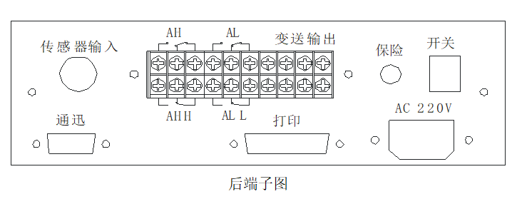
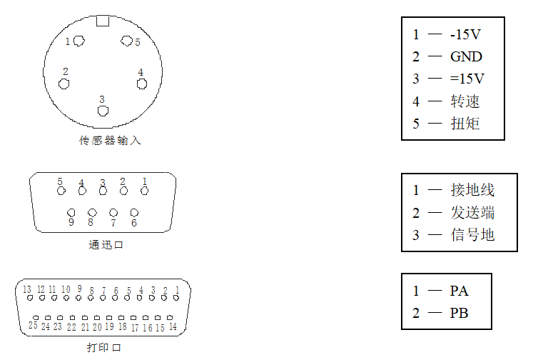
Installation and wiring
1.Outline drawing
2.Terminal diagram
Seventeen, parameters
This table lists the basic parameters of the meter and the parameters related to the options. The parameters related to the options only appear when the meter has the corresponding options.
The \"Explanation \" column is the parameter in the chapter of this manual.
\"Address \" is the address when the computer reads or sets this parameter. Instruments without communication functions are not relevant.
The column\"Value range\" is the setting range of the parameter and the relationship between the parameter content and the value represented by the symbol. Instruments without communication functions are not relevant.
● The first group of parameters alarm set value.
|
symbol |
name |
content |
address |
Ranges |
Description |
|
|
AH |
1st alarm point set value |
01H |
-19999 ~ 45000 |
5.3 |
|
|
AL |
2nd alarm point set value |
02H |
-19999 ~ 45000 |
5.3 |
|
|
LO |
Torque input zero frequency range |
OEH |
0 ~ 50 |
5.1 |
● The second group of parameters alarm status.
|
symbol |
name |
content |
address |
Ranges |
Description |
|
|
OA |
password |
10H |
0 to 9999 |
4.4 |
|
|
ALO1 |
1st alarm point alarm mode selection |
11H |
Note 1 |
5.3 |
|
|
ALO2 |
2nd alarm point alarm mode selection |
12H |
Note 1 |
5.3 |
|
|
HYR1 |
1st alarm point sensitivity |
19H |
Note 1 |
5.3 |
|
|
HYR2 |
2nd alarm point sensitivity |
1AH |
Note 1 |
5.3 |
|
|
CYT |
Alarm delay |
1FH |
0 ~ 20 |
5.3 |
● Third group of parameters Measurement related parameters.
|
symbol |
name |
content |
address |
Ranges |
Description |
|
|
PLuA |
Number of pulses corresponding to 1 unit of rotation |
30H |
1 ~ 9999 |
5.1 |
|
|
in-d |
Decimal point position of speed display |
32H |
1 to 4 (Note 2) |
5.1 |
|
|
in2d |
Decimal point position of torque display |
33H |
0 to 4 (Note 2) |
5.1 |
|
|
Lc |
Torque range |
34H |
100 ~ 10000 |
5.1 |
|
|
AFH |
Speed measurement unit |
35H |
1 |
5.1 |
|
|
in-A |
Speed zero correction |
36H |
0 to 9999 |
5.1 |
|
|
Fi |
Speed range correction |
37H |
0.5000 ~ 1.5000 |
5.1 |
|
|
FLtr |
Speed constant filter time constant |
38H |
1 ~ 20 |
5.1 |
|
|
oYt |
Zero return delay |
39H |
3 ~ 30 |
5.1 |
|
|
At |
Speed display average processing times |
3BH |
1 ~ 20 |
5.1 |
|
|
AT2 |
Torque display average processing times |
3CH |
1 ~ 20 |
5.1 |
● The fourth group of parameters communication, transmission, measurement parameters, etc.
|
symbol |
name |
content |
address |
Ranges |
Description |
|
|
ADD |
Instrument communication address |
40H |
0 ~ 99 |
5.5 |
|
|
bAud |
Communication rate selection |
41H |
Note 4 |
5.5 |
|
|
cLr |
Manual clearance selection |
43H |
Note 3 |
5.1 |
|
|
OA1 |
Whether the first set of parameters is password controlled |
47H |
Note 3 |
4.2 |
|
|
In2d |
Torque zero point correction |
49H |
0 ~ 45000 |
5.1 |
|
|
Fi2 |
Torque range correction |
4AH |
0.5000 ~ 1.5000 |
5.1 |
|
|
FLt2 |
Torque constant filter time constant |
4BH |
1 ~ 20 |
5.1 |
|
|
OP |
Output signal selection |
4DH |
0 ~ 2 |
5.4 |
|
|
bA-L |
Transmission output lower limit |
4EH |
0 ~ 45000 |
5.4 |
|
|
bA-H |
Transmission output upper limit |
4FH |
0 ~ 45000 |
5.4 |
● The fifth group of parameters print and clock.
|
symbol |
name |
content |
address |
Ranges |
Description |
|
|
PO |
Printing method selection |
50H |
0 ~ 3 |
5.6 |
|
|
Pt-H |
Print interval (hours) |
50H |
0 ~ 23 |
5.6 |
|
|
Pt-L |
Print interval (minutes) |
50H |
0 ~ 59 |
5.6 |
|
|
Pt-A |
Print interval (seconds) |
50H |
0 ~ 59 |
5.6 |
|
|
t-Y |
Clock (year) |
50H |
0 ~ 99 |
5.6 |
|
|
t-n |
Clock (month) |
50H |
1 ~ 12 |
5.6 |
|
|
t-d |
Clock (day) |
50H |
1 ~ 31 |
5.6 |
|
|
t-H |
Clock (hour) |
50H |
0 ~ 23 |
5.6 |
|
|
t-F |
Clock (minutes) |
50H |
0 ~ 59 |
5.6 |
Note 1: 0 ~ 1 sequence correspondence 、
、 Alarm mode.
Note 2: 0 ~ 1 sequence correspondence 、
、 、
、 、
、 、
、 。
。
Note 3: 0 corresponds to OFF and 1 corresponds to ON.
Note 4: 0 ~ 3 sequence corresponds to 2400, 4800, 9600, 19200 baud rate.
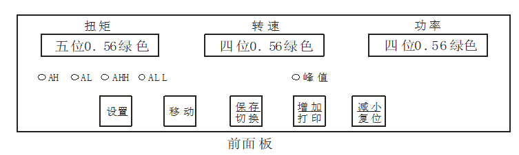
18. Operation
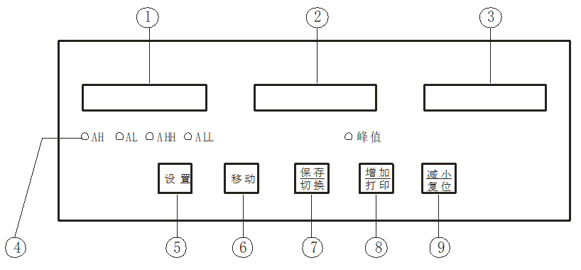
1.Panel and button description
|
name |
Description |
|
|
Display window |
① First display window of measured value |
Display torque measurement · In the parameter setting state, display the parameter symbol and parameter value · The last decimal point flashes to indicate the recording status |
|
Display window |
② Second display window of measured value |
Display speed measurement · Not displayed in the parameter setting state |
|
Display window |
③ The first display window of measured value |
Display power measurement · Not displayed in the parameter setting state |
|
④ Indicator |
Alarm status of each alarm point and display peak mark |
|
|
Operation keys |
⑤ Set up |
· In the measurement state, press and hold for more than 2 seconds to enter the setting state · In the measurement state, when the parameter symbol is displayed, press and hold for more than 2 seconds to enter the next group of parameters or return to the measurement state |
|
⑥ shift key |
Clear peaks during measurement · In the setting state: ① Call up the original parameter value ② Move modification bit |
|
|
确认 Confirmation key |
· Switch the content of the first display window in the measurement state · In the setting state, save the modified parameter value |
|
|
⑧ Increase key |
Start printing in measurement mode Increase parameter value or change setting type in the setting state |
|
|
⑨ Decrease key |
· Reset in measurement state, save torque zero Decrease the parameter value or change the setting type in the setting state |
|
2.Parameter setting instructions
The parameters of the meter are divided into several groups, and each parameter is listed in the group.
The second group and subsequent parameters are controlled by the password. It cannot be entered without a password.
The first group of parameters is controlled by a password and can be selected by setting parameters. When it is set to OFF, it is not controlled by the password. When it is set to ON, if the password is not set, although it can be entered and modified, it cannot be saved.
After entering the setting state, if no key operation is performed for more than 1 minute, the meter will automatically exit the setting state.
3.Setting method of alarm set value
The alarm set value is in the first group of parameters. The instrument without alarm function does not have this group of parameters.
① Press and hold the setting key for more than 2 seconds without releasing it to enter the setting state. The meter displays the symbol of the first parameter.
② Press the confirmation key to select other parameters in this group in sequence.
③ Press the shift key to call up the original set value of the current parameter. The flashing position is the correction position.
④ Move the modification bit by shifting the key, increase the value of the key, decrease the value of the key, and modify the parameter to the required value.
⑤ Press the enter key to save the modified parameters and set other parameters of this group. If it is the last parameter of this group, press the confirmation key to exit the setting state. Repeat steps ② ~ ⑤ to set other parameters in this group.
★ If the modified parameters cannot be saved, it is because the parameter is set to ON, so that this group of parameters is controlled by the password, and a password should be set first.
4. Password setting method
When the meter is in the measurement state or the first group of parameter symbols is displayed, the password can be set.
① Press and hold the setting key until it is displayed.
② Press the shift key to enter the modification state, and modify it to 01234 with the cooperation of the shift key, increase and decrease keys.
③ Press the OK key, and the password setting is completed.
★ The password will be cleared automatically when the meter is powered on or when there is no key operation for more than 1 minute.
5.Setting method of other parameters
① First set the password according to the previous method of \"Password Setting Method\".
② The second group of parameters is the group of the password parameter, and the password is set. Press the OK key to select each parameter of this group.
③ For the parameters of other groups, press and hold the set key without releasing, and enter each parameter group in sequence.
④ After entering the group of the parameter to be set, press the confirmation key sequence to select the parameter to be set in this group.
⑤ Press the shift key to call up the original set value of the current parameter. The flashing bit is the modified bit.
⑥ Move the modification bit by shifting the key, increase the value of the key, decrease the value of the key, and modify the parameter to the required value.
★ The parameter that represents the parameter value in the form of a symbol. When modified, the flashing bit should be at the bottom.
⑦Press the enter key to save the modified parameters and go to the next parameter. ④ ~ ⑦step, set other parameters of this group. Exit setting: When the parameter symbol is displayed, press and hold the setting key until it exits the parameter setting state.
Nineteen, function and corresponding parameter description
1.Measurement and display
The meter measures the input frequency and converts it into torque, speed and power according to the measured parameter content.
The speed parameters include:
● —The number of pulses corresponding to one unit of measurement of the speed, that is, the number of pulses generated by the sensor per revolution.
● —Torque display decimal position.
● -Speed measurement unit, 1 means revolutions per minute.
● —Zero speed correction, display value after correction = display value before correction—
 。
。
● —Speed range correction
 = Actual value / display value.
● -Speed constant filter time constant.
It is used to overcome the jitter of the input signal. Depending on the size of the signal jitter, an appropriate filter constant is selected. When the jitter is severe, the set value can be increased. Generally, it is set to 1.
● —The speed shows the average number of processing times, which is generally set to 1.
It is used to stabilize the display when the signal is unstable. For example, when it is set to 5, the measured values are averaged 5 times before being sent for display.
Torque parameters include
● —The torque input zero frequency range, that is, the difference between the torque input frequency and the zero frequency is within ± LO, and the torque is displayed as zero.
● —Torque display decimal position.
● —Range of torque.
Example: If the value is 100, the range of torque in the range of 5K to 15KHz is -100 to 100.
● —Torque display average processing times, generally set to 1.
It is used to stabilize the display when the signal is unstable. For example, when it is set to 5, the measured values are averaged 5 times before being sent for display.
● —The torque zero point correction is the same as the use of the speed filter constant.
● —Torque range correction, the same as the use of speed filter constant.
● —The torque constant wave time constant is the same as the speed filter constant.
● —Manual clear selection, ON allows manual clearing of the torque and saves the zero frequency.
● —Return to zero delay, that is, when the chip that measures the frequency fails to work normally or is disturbed, the meter will display after waiting for the delay to end—factory setting 3.
Power calculation formula: power = speed display × torque display / 9550.
2.Peak hold function
Press the confirmation key to switch to the peak display. The peak indicator light is on, which means the peak display state is entered. The torque display window displays the peak torque value. Press again to return to the normal display. Press the move key to clear the peak.
3.Alarm output
The meter can be configured with two alarm points, each of which has 3 parameters, which are used to set the alarm value, select the alarm mode and set the alarm sensitivity. However, the alarm sensitivity has been fixed to 0 and cannot be set.
● 、
、 — It is the first and second alarm points.
● 、
、 —Select the alarm mode for the first and second alarm points
Select as Alarm, the upper limit alarm, the alarm when the torque measurement value ﹥ set value.
 Alarm, the lower limit alarm, the torque measurement value 测量 set value alarm.
● Delay for alarm
The setting range is 0 to 20 seconds. When it is 0, there is no alarm delay function.
When the torque measurement exceeds the alarm set value, the alarm delay is started. If the measured value is always in the alarm state during the alarm delay, the alarm signal is output when the alarm delay ends, otherwise the alarm signal is not output.
4.Transmission output
● —Output signal selection
Select as When: the output is 4mA-20mA (or 1V-5V).
 When: The output is 0mA-10mA.
 When: the output is 0mA-20mA (or 1V-5V).
● —Transmission output lower limit.
● —Transmission output upper limit.
Example: If the output is required to be 4mA-20mA, corresponding torque value is 0 ~ 25000, then set =
= ,
, =
= ,
, =
= 。
。
★ The transmission output is the absolute value of the torque, that is -100 and 100 are the same.
5.Communication interface
● —Instrument communication address, factory setting is 1.
● —Communication rate selection, factory setting is 4800bps, no check.
Communication command (A-meter communication address):
# AA↙ Read torque value
# AA00↙ Read torque value
# AA01↙ Reading speed value
# AA02↙ Reading power value
# AA03↙ Reading the peak value
6.Printing interface
● —Communication rate selection, factory setting is 4800bps.
● —Printing mode selection
When 0 is selected: Does not print.
1 hour: print key to start printing.
2 o'clock: print key + timing to start printing.
3 o'clock: print key + timer + alarm to start printing.
● 、
、 、
、 The time interval is hour, minute, and second.
● There are 5 parameters for setting and calibrating the internal clock of the instrument.
 、
、 、
、 、
、 、
、 They are year, month, day, hour, and minute.
★ The printer is a Xunpu miniature Chinese character library wide paper printer.
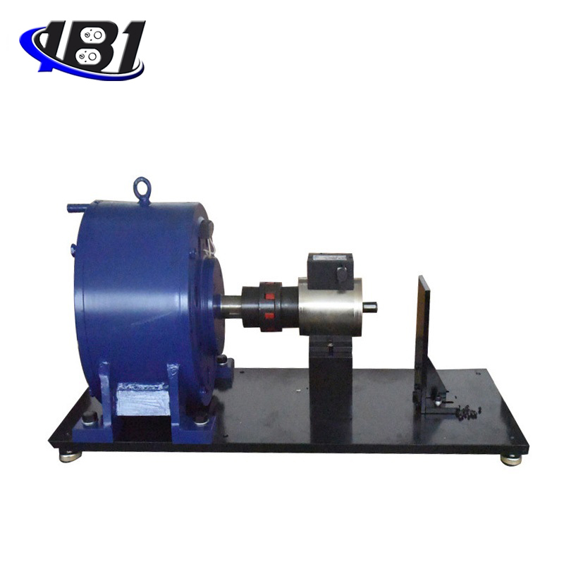
Ⅲ, magnetic powder brake
Twenty, shaft coupling, base support magnetic powder brake (this product is optional)
When the rated torque is greater than 400N · m, the rated voltage is DC36V, and the remaining rated voltage is DC24V.
|
specification model |
Rated Torque N · m |
Slip power Kw |
excitation Current A |
Allowed Rotating speed r / min |
Dimensions |
Shaft coupling size |
Base support size |
cool down the way |
|||||||||
|
H |
L |
d ( h7) |
b ( p7) |
L1 |
L2 |
L3 |
L4 |
L5 |
L6 |
H1 |
d1 |
Naturally cold |
|||||
|
FZ2.5.J |
2.5 |
0.1 |
0.4 |
1500 |
110 |
85 |
10 |
3 |
20 |
6 |
50 |
68 |
100 |
120 |
60 |
7 |
Naturally cold |
|
FZ5.J |
5 |
0.3 |
0.5 |
1500 |
138 |
94 |
12 |
4 |
25 |
10 |
50 |
68 |
120 |
140 |
75 |
7 |
Naturally cold |
|
FZ10.J |
10 |
0.8 |
0.6 |
1500 |
166 |
96 |
14 |
5 |
25 |
6 |
60 |
85 |
120 |
150 |
90 |
10 |
Naturally cold |
|
FZ25.J |
25 |
2 |
0.8 |
1500 |
196 |
109 |
20 |
6 |
36 |
8 |
70 |
96 |
150 |
180 |
110 |
12 |
Naturally cold |
|
FZ50.J / Y |
50 |
4 |
1 |
1500 |
240 |
133 |
25 |
8 |
42 |
11 |
80 |
105 |
180 |
210 |
130 |
12 |
Single water cooling |
|
FZ100.J / Y |
100 |
7 |
1.2 |
1500 |
284 |
233 |
30 |
8 |
58 |
14 |
100 |
130 |
250 |
290 |
155 |
12 |
Double water cooling |
|
FZ200.J / Y |
200 |
10 |
1.8 |
1000 |
329 |
244 |
35 |
10 |
58 |
12 |
120 |
165 |
280 |
330 |
180 |
15 |
Double water cooling |
|
FZ400.J / Y |
400 |
12 |
2.5 |
1000 |
400 |
298 |
45 |
14 |
82 |
22 |
130 |
180 |
330 |
390 |
215 |
15 |
Double water cooling |
|
FZ630.J / Y |
630 |
15 |
2.5 |
750 |
441 |
353 |
60 |
18 |
105 |
20 |
150 |
210 |
410 |
480 |
240 |
19 |
Double water cooling |
|
FZ1000.J / Y |
1000 |
20 |
2.5 |
750 |
523 |
390 |
70 |
20 |
105 |
35 |
160 |
210 |
470 |
540 |
280 |
19 |
Double water cooling |
|
FZ2000.J / Y |
2000 |
30 |
3 |
450 |
619 |
468 |
80 |
22 |
130 |
54 |
170 |
240 |
580 |
660 |
330 |
24 |
Double water cooling |
|
FZ5000.J / Y |
5000 |
50 |
3 |
300 |
824 |
566 |
90 |
25 |
140 |
13 |
320 |
388 |
600 |
700 |
430 |
24 |
Double water cooling |
|
FZ10000.J / Y |
10000 |
60 |
4 |
250 |
1126 |
611 |
120 |
32 |
160 |
18 |
360 |
450 |
900 |
1030 |
600 |
28 |
Double water cooling |
|
FZ20000.J / Y |
20000 |
75 |
5 |
200 |
1620 |
850 |
155 |
40 |
180 |
105 |
400 |
550 |
1300 |
1450 |
750 |
34 |
Double water cooling |
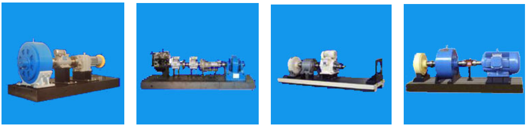
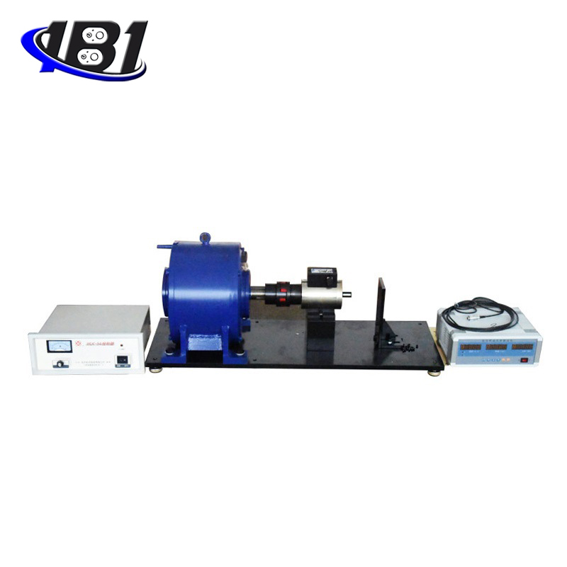
Ⅳ 、 Test case
The diagrams of the 21st and 4th test cases are as follows