support hotline
0577-57572522
First, the function
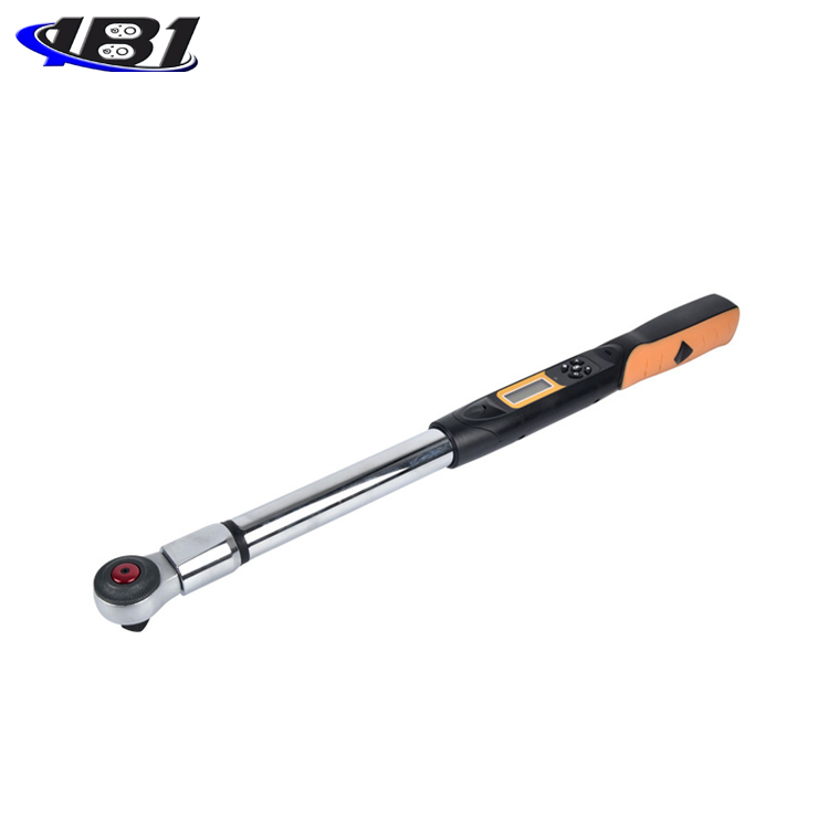
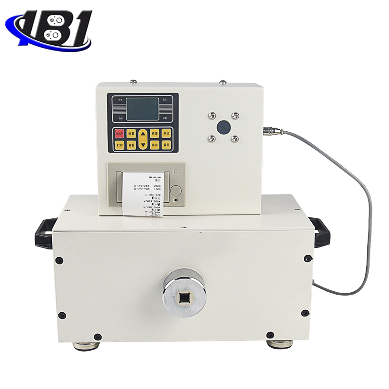
Digital torque tester is an intelligent multifunctional measuring instrument designed and manufactured for testing and detecting various torques. It is mainly used to detect and correct the torque of various electric pneumatic screwdrivers and torque wrenches. Various products involve the test of tightening force and the destructive test of parts torsion. It has the characteristics of simple operation, high precision, full functions, and convenient portability. It is widely used in various electrical, light industry, machinery manufacturing, scientific research institutions and other industries.
Specifications
|
model
index |
With printer |
ENL-1P |
ENL-2P |
ENL-3P |
ENL-5P |
ENL-10P |
ENL-20P |
|
Without printer class |
ENL-1 |
ENL-2 |
ENL-3 |
ENL-5 |
ENL-10 |
ENL-20 |
|
|
measuring range / Minute Degree value |
N · m |
1.000 / 0.001 |
2.000 / 0.001 |
3.000 / 0.001 |
5.000 / 0.001 |
10.00 / 0.01 |
20.00 / 0.01 |
|
Kg · cm |
10.20 / 0.01 |
20.40 / 0.01 |
30.60 / 0.01 |
51.00 / 0.01 |
102.0 / 0.1 |
204.0 / 0.1 |
|
|
Ib · in |
8.85 / 0.01 |
17.70 / 0.01 |
26.55 / 0.01 |
44.25 / 0.01 |
88.5 / 0.1 |
177.0 / 0.1 |
|
|
Precision |
± 1% |
||||||
|
Peak sampling frequency |
1920HZ |
||||||
|
power supply |
8.4V 1.2VX7 Ni-MH battery pack |
||||||
|
Charging time |
4 to 6 hours |
||||||
|
Battery continuous use time |
About 10 hours |
||||||
|
Battery Life |
≥300 times |
||||||
|
size |
With printer: 350mm × 190mm × 180mm Without printer: 123mm × 230mm × 65mm |
||||||
|
Net Weight |
With printer: 34KG Without printer: 2KG |
||||||
|
charger |
Input: AC 220V 50HZ Output: DC 10V 300mA |
||||||
Third, the main features
1. High precision, high resolution, fast sampling speed, full screen display.
2. High precision torque sensor with torque direction display.
3. Setting of upper and lower limits, red and green indicator lights and audible and visual alarms of the peak sounder.
4. Three types of units can be converted to each other for selection (N · m, kgf · cm, Ib · in).
5, real-time, peak, automatic peak three modes can be switched at will.
6. The USB interface is used to communicate with the PC. The synchronous test function can be connected to a computer test. The computer displays the test force curve diagram and the detailed test force record during the test, and can save, print, and perform various analyses.
7, peak hold, automatic release function, release time freely set.
8, large storage capacity, can save 99 sets of test data.
9. Automatic shutdown function without operation, time can be set freely.
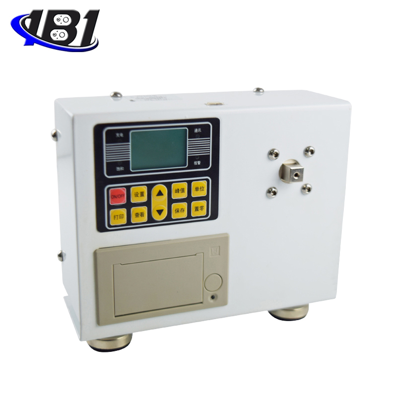
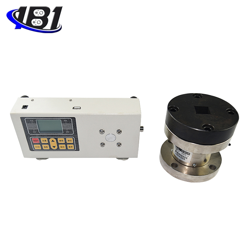
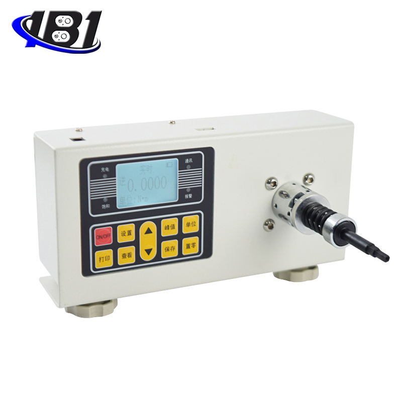
Product schematic diagram
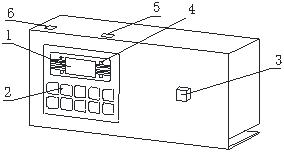
1. LCD display 2. Function buttons 3. Torque test head
4.Display light 5.USB interface 6.Power socket
Five: display panel
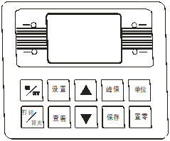
Six: Button description
1. Setting key: The user can enter the setting menu through this key in the measurement interface, and press this key to save the data when setting the data.
2. View key: Use this key to view the stored measurement data during the measurement interface.
3. Peak key: used to switch between three real-time, peak, and automatic peak measurement modes.
4. Save key: used to save the measured data.
5. Unit key: Used to switch between N · m, kgf · cm, and Ib · in.
6. Zero-setting key: During real-time measurement, press this key to correct the zero point. During the peak and automatic peak, press this key to clear the peak value and return to zero; when viewing the interface, press this key to clear the current stored measurement value, and long press this key to clear all stored measurement values. In the user setting interface, press this key to return to the previous interface without saving data.
7. Print key: In the measurement interface, press this key to print the stored measurement value (except those without print function).
8. Up key: In the user setting interface, press this key to modify the setting items up and down. During parameter setting, press this key to move bit by bit to select the number of digits to be modified. In the viewing interface, press this key to view the upper bits. One data.
9. Down key: In the user setting interface, press this key to modify the setting items downwards. During parameter setting, press this key to modify the data in the current position; in the viewing interface, press this key to view the next data.
10. ON / OFF key: can be used to turn on and off.
Seven: User operation instructions
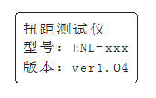
1. Startup display
Startup display welcome and manufacturer information

Display product name, model and version information
2. User main interface display
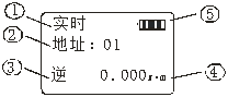
The content displayed on the first line can be divided into three types: real-time, peak, and automatic peak according to the measurement mode set by the user;
The content displayed in the second line is the data address stored by the user;
The third line shows the force value currently measured.
3. User setting interface
Press the setting key once, as shown below:

Select the setting item through the up or down key. When the user's setting item is selected, press the setting key to enter the parameter setting interface.
4.Parameter setting interface
In the user setting interface, press the setting key to enter the parameter setting interface, which is displayed as follows:

Setting parameter description: (the upper limit is set as an example)
Use the up and down keys to shift and modify the data. At this time, press the set key to confirm and save the set data (such as pressing the zero key to return without modifying the data). The set data cannot exceed the maximum load value.
4.1. Upper limit value setting: The user sets the upper limit value, which can be set freely according to the needs. When the upper limit value is reached, the audible and visual alarm is automatically performed.
4.2. Setting of lower limit value: The user sets the lower limit value, which can be set freely as required. When the lower limit value is reached, an automatic light alarm is issued.
4.3. Minimum storage value setting: The user sets the minimum storage value according to the storage needs. Data smaller than this value will not be stored.
4.4. Minimum peak hold value setting: The user needs to set freely according to the peak value, automatic peak measurement, and data less than this value is not saved by the peak value.
4.5. Automatic peak time setting: The user can freely set the time from 1 second to 99 seconds according to the peak value in the automatic peak measurement state.
4.6. Automatic shutdown time setting: In the non-operation state, the automatic shutdown time can be freely set from 1 minute to 99 minutes.
4.7 Gravity acceleration setting: The user can set the gravity acceleration value according to the location of the area. The default value of this machine is 9.794.
4.8. Restore the initial settings: Improper user operations or changes to data that appear to be confusing. You can use this setting to restore the data to the factory state.
4.9 Sensor calibration: the user enters the password after pressing the\"\" Set\"key\" 、
、 , Peak, save,、, Peak, Save \"to enter the calibration setting interface, as shown in the figure below:
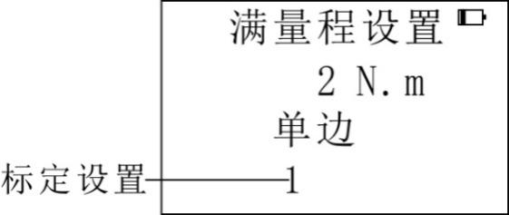
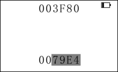
The user can set \"calibration setting \" according to the needs, press \"setting \" key to select \"1 \" (full scale calibration), \"1/2 \" (1/2 calibration), \"1 / 4 \"(1/4 calibration), \" 1/8 \"(1/8 calibration); after selecting, press \" Save \"key to enter the calibration interface. After calibration, press \" Save \"key to save , And finally press the\"\" ON / OFF \"key to shut down. As shown below:
4.10. Language: The instrument has Chinese and English languages for users to choose. Press the\"\" Setup\"\" key to enter the\"\" Language\"\" selection. After pressing the\"\" Save\"\" key, the instrument saves the selected language and automatically shuts down. If you need to use it, you can restart it.
Eight, other function description
1. Description of printing function: print data through micro printer.
2. Communication: communicate with the host computer via USB. The communication protocol is MODBUS-RTU protocol.
3. Save data: Save the data during measurement by the save key.
4. View stored data: View the stored data through the View key.
5. Alarm description: When the measured value exceeds the upper limit, the upper limit indicator will be displayed, and the buzzer will also alarm; when the measured value is lower than the lower limit, the lower limit indicator will be displayed. When the measured value exceeds 120% of the maximum load, it may cause damage to the sensor. When the measured value exceeds 150% of the maximum load, it will definitely cause system damage. When \"Overload \" warning prompt appears, the machine enters the automatic protection state and must be restarted. If it cannot be measured, press and hold the setup key, enter the password: up and down keys, press the setup key to enter the factory reset interface Select Restore factory settings and press the Set button to restore (if you cannot restore, please contact the manufacturer).
Nine, operating environment
1. Operating temperature: -10 ℃ ~ 40 ℃.
2. Operating humidity: ≤90% RH.
3. There is no vibration source and no corrosive environment around.
X. Operating steps
1. Before using the digital torque tester, check whether the power of the instrument is sufficient. If the power is insufficient, charge it first (it can also be used when charging).
2. Under normal circumstances, turn on the power switch and the displayed torque value is zero. If it is not zero, press the zero key to clear the torque value.
3. According to the test needs, press the moment unit conversion button to select the required unit
4. Set up before testing. The specific steps are as parameter setting interface.
Eleven, test range, installation and inspection of the buffer
1. Test range of the buffer
|
model |
Buffer test range |
Note |
|
ENL-3, ENL-5, ENL-10, ENL-20 |
0.5-3N.m |
Use a spring with a wire diameter d = 3.5 |
|
ENL-1, ENL-2 |
0.15-0.6N.m |
Use a spring with a wire diameter d = 2.5 |
2. Installation of the buffer: According to the needs of the test, select the bearing and spring, then rotate it counterclockwise to install the spring.
3. Inspection of the buffer:
A. Check the buffer before use. Dust, lack of grease and bending of the sleeve will affect the accuracy of the torque test.
B. Check the buffer regularly, and use the buffer repeatedly for a long time will cause the wear of the buffer and affect the accuracy of the torque test.
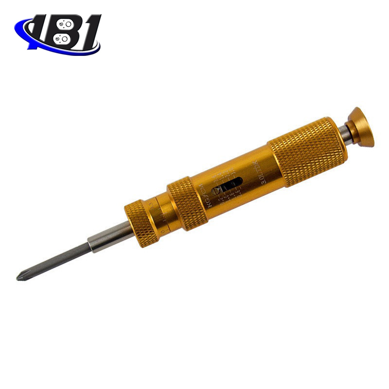
Twelve screwdriver torque test procedures
1. Install the buffer on the torque test head of the torque tester, and then assemble the screwdriver batch on the buffer.
2. Press the switch of the screw to the automatic state, use your fingers to reverse the force, and relax the spring of the buffer a little.
3. Press the peak key to select the PEAK peak hold state.
4. Press the zero key, the torque value on the LCD screen is zero.
5. Press the switch of the screwdriver to automatic, twist the screwdriver until the screwdriver stops automatically.
6. When the screwdriver stops rotating, the torque value displayed on the LCD screen is the torque output by the screwdriver. Repeat the above 2-5 operation to verify the output torque of the screwdriver. Loosen or tighten the torque adjustment nut of the screwdriver so that the torque of the screwdriver meets the needs of use.
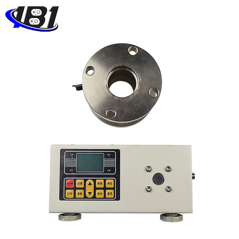
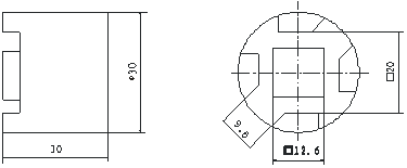
Thirteen, torque test head and connection size
1. When in use, install the bumper on the torque test head completely.
2. The vertical load on the torque test head cannot exceed 10kg.
3. Do not bump the test head of the torque tester to avoid damage. The following is a plan view of the torque test head:
Fourteen, matters needing attention, maintenance and repair
1. Don't test the torque by overload. Be sure to test the torque within the test range of the torque tester, otherwise it will damage the instrument and may cause danger.
2. Do not tap the LCD screen and place objects on the LCD screen.
3. Do not press the function keys with nails, sharp objects or pointed objects.
4. Do not use the torque tester in places where water, oil or other liquids are splashed. Store the torque tester in a cool, dry and vibration-free place.
5. Do not open the small cover on the back, nor can you adjust the trimmer resistor inside.
6. Do not loosen the fixing screws of the torque test head.
7, please use the matching charger to charge, otherwise it will cause circuit failure or even fire.
8. Insert the AC charger completely into the socket before using it. Loose plugs may cause short circuits and cause electric shock or fire.
9. Do not use any power source other than the rated voltage of the charger, otherwise it may cause electric shock or fire.
10. Please do not pull out or insert the plug with wet hands, otherwise it may cause electric shock.
11. Please use a soft cloth to clean the machine, immerse a dry cloth in water soaked with detergent, wring it dry, and then remove dust and dirt. Do not use chemicals that emit easily, such as volatile oils, thinners, alcohol, etc.
12. Handle gently during use and handling.
13. Do not disassemble, repair or modify the machine yourself. These actions may cause permanent failure of the instrument.
14. If any trouble occurs, please contact the place of purchase or the company.
15. Within one month from the date of sale of this product, product quality problems have occurred under normal use and no damage to the appearance. The customer should bring the original sales invoice, valid warranty card and complete packaging to the original place of purchase or the company will replace the same specifications Model products, the replacement products continue the warranty period and terms of the original product.
16. Within one year from the date of sale of this product, under normal use, non-man-made faults are covered by the warranty (the user disassembles the machine or repairs at other service points by the company without warranty), and the customer has the original sales invoice and the valid warranty Contact the original place of purchase for a free one-year warranty.
17. The warranty terms of this product are only applicable to ENL series products sold in the Chinese market. For products that exceed the replacement period and warranty period, customers can inquire about maintenance issues at the original place of purchase or contact the company, and the company will provide paid maintenance .