support hotline
0577-57572522

I. Features
1.1 With high precision and high resolution: large screen LCD display, with backlight function (backlight suitable for night use), and with screen digital forward and reverse function;
1.2 With battery capacity display: divided into 3 grids, 2 grids and 1 grid, the instrument will automatically shut down when the battery is too low;
1.3 With gravity acceleration setting function: users can enter the precise value of gravity acceleration of the place of use by themselves, making the test more accurate;
1.4 With peak hold function: keep the peak display until it is manually cleared;
1.5 With automatic peak function: keep display peak time adjustable;
1.6 has a large memory storage function: can store 447 test values;
1.7 With data output function: data can be input to the computer through the data line for various analyses;
1.8 With automatic shutdown time setting: The automatic shutdown time can be set to automatically shut down from 10 minutes to 90 minutes;
1.9 With high-quality charging power supply: the charging voltage is available from 100V to 240V, which can be adapted to most areas at home and abroad;
Technical parameters
2.1 Model: DYD-2;
2.2 Maximum load: 100Kg (Kg, N and Lb units can be freely converted);
2.3 Resolution: 0.01Kg;
2.4 Accuracy: ± 1%;
2.5 Measuring depth: 0 ~ 450mm;
2.6 Power source: Charging power source: 220V / AC; Battery continuous working time: 6 ~ 8 hours;
2.7 Stability: Temperature drift: 0.2uV / ° C (0-60 ° C); Zero drift: ≤ 0.1% / 8 hour / F · S;
2.8 Calibration range: full scale calibration;
2.9 Ambient temperature: 0 ~ + 60 ℃;
2.10 Ambient humidity: ≤ 80%;
2.11 Allowed overload: 150%;
2.12 Power supply mode: Ni-Cyan battery pack / 220V AC charge for 4 ~ 6 hours.
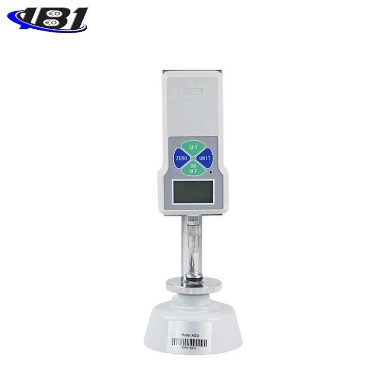
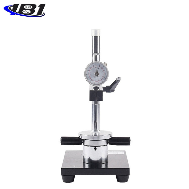
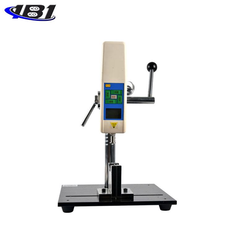
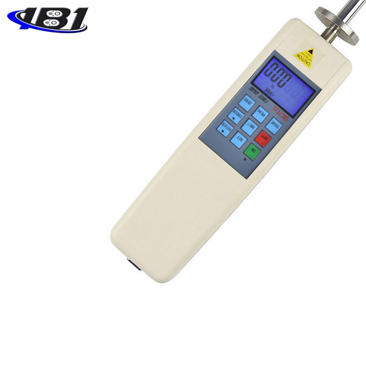
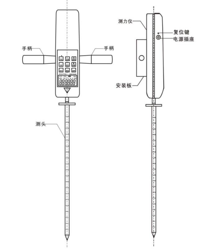
Structure diagram
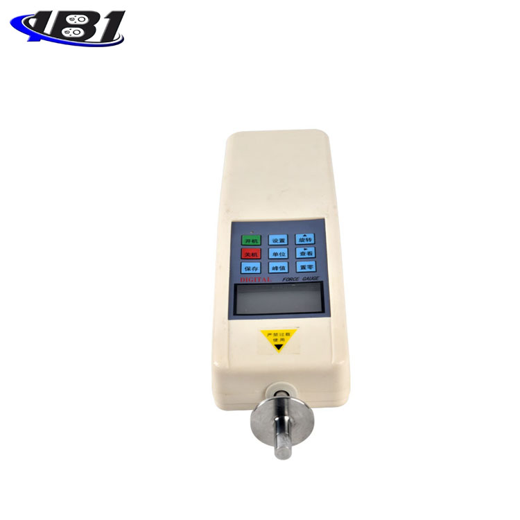
Fourth, the button description
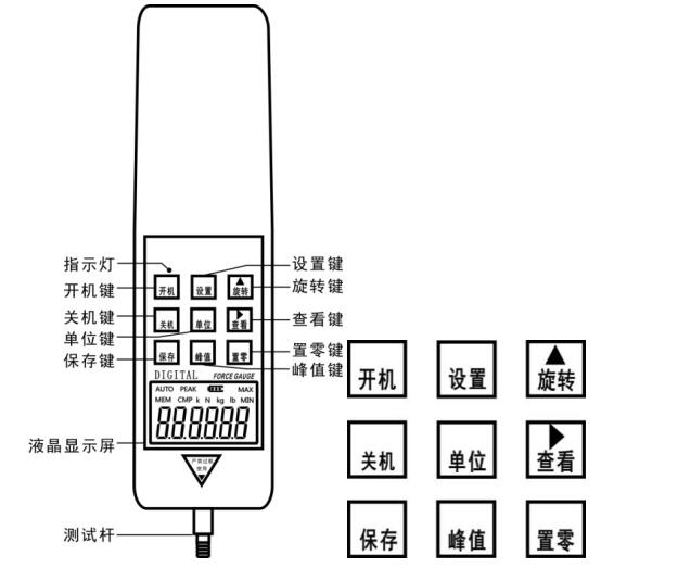
4.1 \"Startup \" key:
When you press this key, the power is turned on and the model number is displayed. After powering on, before pressing the\"\" Zero\"key\" to clear, the zero drift value of the analog signal may be displayed on the screen, just press the\"\" Zero\"key\" to clear it.
4.2 \"Shutdown \" key:
In the power-on state, when you press this key, the power is turned off, but the stored saved data will not disappear. When starting up (that is, when the model number is displayed and the measurement interface 0.0 is not displayed), pressing the shutdown key at this time cannot respond.
4.3 \"Save \" key:
In the peak measurement interface state, press this key to save the test data displayed on the screen; in the function setting interface state, press this key to save the set parameters. When some test data is stored in the machine, \"MEM \" is displayed. This machine can store 447 data.
4.4 \"Peak \" key:
Each time you press this key, there will be a switch between \"PEAK \" display, \"AUTO PEAK \" display or \"PEAK \" disappearing—that is, peak hold, peak hold automatic release, and load real-time value mode switching.
4.5 \"Unit \" key:
Press this key to execute the measurement unit switch, which can display three units of N (Newton), kg (kg) and lb (pound) in a cycle. When the test data is displayed, the unit conversion of the same value can also be completed.
4.6 \"Settings \" key:
In the real-time measurement interface, press this key to enter the setting item interface; in the setting item interface, press this key to enter the required setting option.
4.7 \"Rotate \" key:
This key is only valid in the test interface. When this key is pressed, the measured value displayed on the screen will flip 180 degrees.
4.8 \"View \" key:
When you press this key, the stored test data will be called up and displayed on the screen in sequence. At this time, the word\"\" MEM\"\" will flash-the number of saves will be displayed first, and the saved data will be automatically displayed after 2 seconds. Press the\"Zero Set\" key to return to the measurement interface.
4.9 \"Zeroing \" key
When this key is pressed in the measurement interface, the test value on the screen will be reset to zero.
※ Select a lighter fixture or release the applied load and clear it again.
※ In the view of stored data interface, press and hold this key for 4 seconds, all stored test data can be cleared (it may not be cleared in some states, restart the machine after powering off and then execute this function to clear all the saved data).
Five, screen display instructions
5.1 PEAK
When \"PEAK \" is displayed, it means Peak mode, and the display shows the peak value until it is manually cleared. When \"AUTO PEAK \" is displayed, it means \"auto peak \" (Peak hold automatic release mode) ), The default display peak value is automatically cleared after 5 seconds; when \"PEAK \" is not displayed, it means \"track mode \" (real-time load value mode), and the value on the screen changes with the change of load;
5.2 MEM
When data is stored,\"MEM\" is displayed; when you press the\"View\" key to view the stored data,\"MEM\" flashes.
Six, stored data
6.1 Stored data
In the PEAK state, after the test is completed, press the\"Save\" key to store the data. The display will show\"MEM\" on the display. The stored data can be saved even after the power is turned off. When you use the\"\" View\"\" key to view the stored data,\"\" MEM \"flashes, the number of times of storage appears first, and the stored value automatically appears after 1 second. Press the\"Zero Zero\" key to return directly to the measurement interface. The data can also be input into a computer for analysis and processing. This machine can store 447 data.
6.2 Clearing stored data
When pressing the\"\" View\"\" key to enter the stored data interface, press the\"\" Zero\"\" key for more than four seconds, all the stored data will be cleared,
\"MEM \" disappears.
This machine can be connected to a computer and enter test data into the computer. View and print the number of tests, average, maximum, minimum, and determine whether the test results meet the set requirements.
7. Other functions:
7.1 Printing function description:
This function can output the stored test data to a computer through a data cable for printing.
a. First run the CD that came with the machine, open the resulting folder, click the\"data export program\" file, then click the\"setup.exe\" file, and then click\"Next\" →\"Next\" Step \"→ \" Done \".
b. Connect the instrument to the computer with a data cable. When the instrument is powered on, when the LCD screen shows zero, double-click the \"dynamometer communication software 3.0.exe \" shortcut key on the desktop, and then Click \"Receive \" in the pop-up window, and the stored test data will be output to the computer through the data cable. After receiving the data, click \"Print \", and click Print in the pop-up window to print.
7.2 Synchronous test function description:
This function can display the synchronous test curve and data during the test. After running the CD-ROM that came with it first, it will be in the folder. After opening, click the\"\" Sync test software\"\" file, then click the\"\" Install.EXE\"\" file, and then click\"\" Next\"\" → \"Next \" → \"Done \".
7.3 Explanation of Overloading Status:
When the alarm is turned on and the display data cannot be cleared.
Approach:
Restore the factory settings (if unable to restore, you need to return to the factory to replace the sensor).
7.4 Instructions for solving the crash state:
When the measuring instrument freezes, press the\"\" Reset\"\" key on the left side of the measuring instrument.
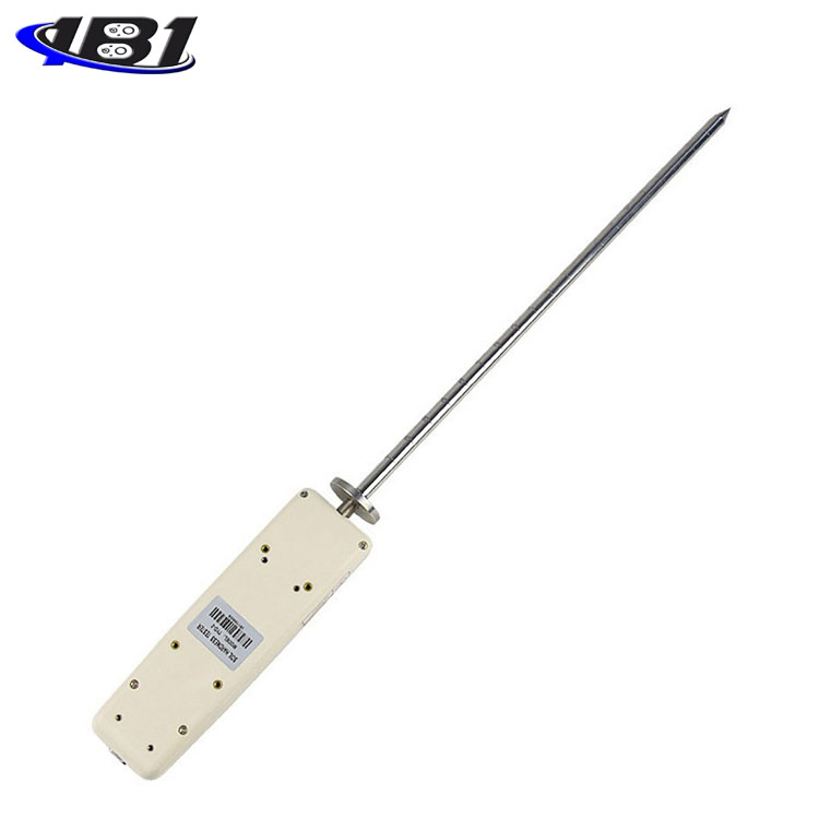
Test: (refer to the structure diagram)
8.1 Preparation before measurement:
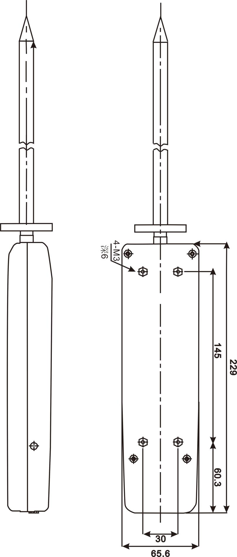
a. Use four M4 screws to install the mounting plate and the adapter plate firmly, and then use four M3 screws to install the dynamometer and the adapter plate firmly;
b. Connect the probe to the dynamometer and let it tighten;
c. Level the soil surface to be measured.
8.2 During measurement:
a. First press the\"On\" key to turn on the power of the instrument. After the LCD display is stable, press the\"Peak\" key to enter the peak measurement mode (if the display is not zero, press the\"Zero\" key (Cleared); then hold the handle of the instrument with both hands and insert the tip of the instrument into the soil (during the insertion of the soil, if the tip of the instrument hits objects such as stones and tree roots, please pull out the instrument, (Re-measurement), the insertion depth depends on the customer's needs.
b. After the measurement, read the measured value.
Nine, gravity acceleration setting:
The user of this machine can input the gravity acceleration value of the place of use. Press \"Settings \" key to enter the setting interface, select (G.SET) Enter. After entering the required gravity acceleration value, press \"Save \" key to save the setting and return to the setting interface.
Ten, installation precautions
Precautions
Incorrect operation may damage the instrument or cause serious accidents. This manual points out important matters to prevent accidents and how to use the instrument. Please read this manual carefully before use, and keep it in a safe place for future reading.
Cautions
1. Do not use the instrument beyond its maximum range. Doing so may cause damage to the sensor or even an accident.
2. When the test value exceeds 105% of the range, the buzzer will beep continuously. In this case, please quickly release the added load or reduce the load.
Safety Precautions
1. Please use the matching charger to charge, otherwise it will cause circuit failure or even fire.
2. Do not use a power source other than the rated voltage of the charger, otherwise it may cause electric shock or fire.
3. Do not pull out or insert the plug with wet hands, otherwise it may cause electric shock.
4. Do not pull the power cord of the charger to pull out the plug, so as to avoid the electric wire being torn and getting an electric shock.
5. Please use a soft cloth to clean the machine. Immerse the cloth in water soaked in detergent and wring it dry before removing dust and dirt.
Note: Do not use volatile chemicals to clean the machine (such as volatile agents, thinners, alcohol, etc.)
6. Do not operate the machine in the following environments
(1) Humid environment (2) Dusty environment
(3) Where oil or chemicals are used (4) Where there are earthquake sources around
7. Please use and store within the specified temperature and humidity range, otherwise it may cause the instrument to malfunction.
8. Do not disassemble, repair or modify the machine yourself. These actions may cause permanent failure of the instrument.
9. Other outstanding matters needing attention in safety production.
Eleven other matters needing attention
Confirmation items before sending the soil hardness meter for repair
|
power supply |
symptom |
Cause or phenomenon |
Dispose |
|
Press \"Startup \" key no display |
Battery is dead |
Recharge |
|
|
Unable to charge |
Charging specifications Nonconforming converter |
Please confirm: AC110V → DC12V AC220V → DC12V |
|
|
test value |
Test value is not accurate |
Excessive error |
Weight correction reading |
|
other |
Parameter confusion |
MODE setting error |
Press \"Settings \" to switch to factory reset, then press \"Settings \". |
|
Unexpected crash |
No response by pressing any key |
Restart after pressing the reset button |
Special Note:
Digital soil hardness tester has many specifications for users to choose. Users can choose the corresponding specifications of the instrument according to the force value of the product to be tested. The scientific use test range is from 10% to 100% of full scale. The metrology department recommends not to use less than 1% of full scale.
Twelve installation dimensions
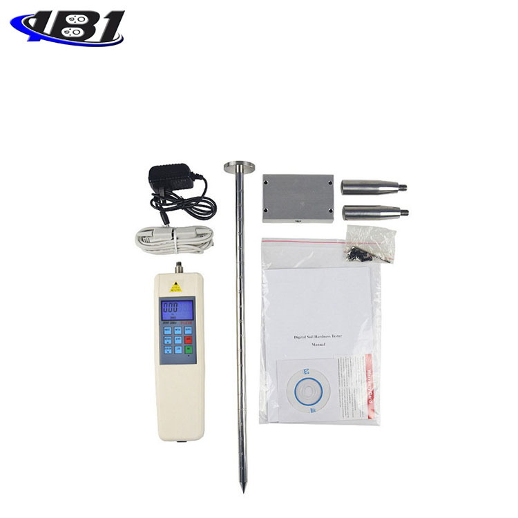
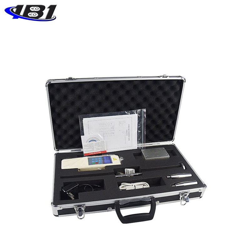
Thirteen, packing list
|
Serial number |
name |
Quantity |
|
1 |
Digital display |
1 set |
|
2 |
Probe |
1 item |
|
3 |
Digital display meter mounting block (aluminum four squares) |
1 |
|
4 |
Adapter board |
1 |
|
5 |
handle |
2 pieces |
|
6 |
charger |
1 item |
|
7 |
RS232 computer connection cable |
1 |
|
8 |
M4 Allen wrench |
1 |
|
9 |
M4 * 10 Hex Socket Head Cap Screws |
4 |
|
10 |
M3 * 8 Hex Socket Head Cap Screws |
4 |
|
11 |
φ4 elastic washer |
4 |
|
12 |
Certificate of conformity and warranty card |
1 piece |
|
13 |
Manual |
1 serving |
|
14 |
Inspection certificate |
1 serving |
|
15 |
Supporting software CD |
1 piece |
|
16 |
Desiccant |
1 package |