support hotline
0577-57572522
TOC \ o \"1-3\" \ h \ z1 Overview3
1.1 Technical parameters …………………………………… ..3
3 Preparation before measurement9
3.3 Surface treatment of the tested workpiece9
4.1 Switching the instrument on and off9
5 Measurement application technology13
5.2 Pipe wall measurement method14
6 Maintenance and precautions14
6.3 Precautions during measurement14
6.4 Cleaning of standard test blocks15
7 Storage and transportation conditions15
Appendix A Material Sound Velocity16
Appendix B Common Problems and Solutions in Ultrasonic Thickness Measurement17
Configuration list ... ………………………………………… 23
Notice to users ……………………………………………… 24
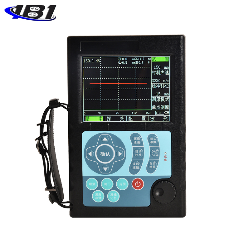
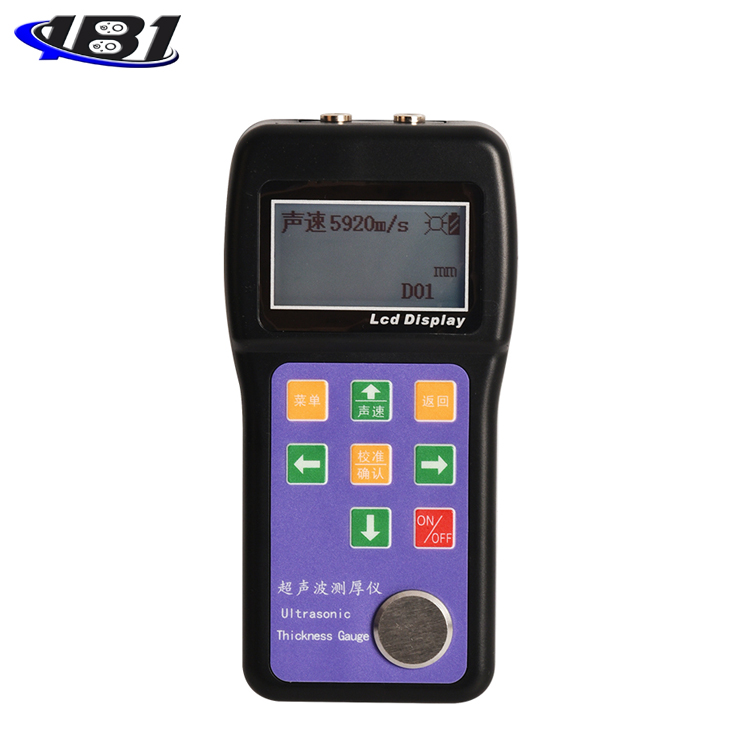
This instrument is intelligentUltrasonic Thickness GaugeUsing the latest high-performance, low-power microprocessor technology, based on the principle of ultrasonic measurement, it can measure the thickness of metals and other materials, and can measure the speed of sound of materials. It can monitor various pipes and pressure vessels in production equipment, monitor their thinning degree after being corroded during use, and can also accurately measure various plates and various processed parts. This instrument can be widely used in various fields such as petroleum, chemical industry, metallurgy, shipbuilding, aviation, aerospace and so on.
1.1 Technical parameters:
|
project |
unit |
Performance indicators and functions |
|
Display method |
High contrast 128 * 64 liquid crystal display, high brightness EL backlight; |
|
|
Measuring range |
mm |
0.75 ~ 600.0 (steel) |
|
Material sound velocity |
m / s |
1000 ~ 9999 |
|
Resolution |
mm |
0.01 |
|
Indication accuracy error |
mm |
When the measurement range is 0.75 to 3.3, the resolution is 0.01 and the allowable error is ± 0.05. When the measurement range is 3.3 to 99.99, the resolution is 0.01 and the allowable error is ± (1 ‰ H + 0.04). When the measurement range is 100.0 to 300.0, the resolution is 0.01 and the allowable error is ± 3 ‰ H measurement range 300.0 ~ 600.0, resolution 0.01, allowable error ± 5 ‰ H Note: H is the thickness of the measurement |
|
Measurement cycle |
Single point measurement 6 times per second; |
|
|
Calibration mode |
4mm automatic calibration with machine test block / user-defined calibration (single-point calibration / double-point calibration) |
|
|
Measurement function |
Software functions such as minimum reading capture, average measurement, limit measurement, and difference measurement are optional |
|
|
Measurement mode |
R-B1 (transmit pulse to one echo) |
|
|
Dynamic sound speed measurement |
Can use the known thickness to dynamically scan and read the sound velocity of the measured workpiece |
|
|
Intelligent power function |
After being idle for a period of time, the instrument will automatically shut down. |
|
|
buzzer |
Calibration tips, over-limit tips |
|
|
storage |
40 sets of thickness measurement data (only measured values, sound velocity values) 40 sets of parameter data sets (including measured values, instrument settings and other parameters) |
|
|
Language |
Chinese / English optional |
|
|
Unit system |
Metric (mm) / Inch (inch) optional |
|
|
operating hours |
h |
≥30 |
|
Power supply mode |
Two AA batteries |
|
|
Operating temperature |
℃ |
-10 ~ 40 |
|
weight |
g |
About 245g (including battery) |
|
size |
mm |
145mm × 74mm × 32 mm (height × width × thickness) |
Suitable for measuring the thickness of metals (such as steel, cast iron, aluminum, copper, etc.), plastics, ceramics, glass, fiberglass, and any other good conductor of ultrasound;
Can be equipped with a variety of dual-frequency probes with different frequencies and different chip sizes;
Known thickness can inverse measure sound speed to improve measurement accuracy;
Coupling status prompt function;
EL backlight display, easy to use in dim light environment;
With remaining power indicator function, it can display the remaining battery power in real time;
With power saving functions such as automatic hibernation and automatic shutdown;
Compact, portable, high reliability, suitable for harsh operating environment, resistant to vibration, shock and electromagnetic interference;
For the thickness measurement of this ultrasonic thickness gauge, the ultrasonic pulse generated by the probe passes through the couplant to reach the test object. Part of the ultrasonic signal is reflected by the bottom surface of the object. The probe receives the echo reflected by the bottom surface of the test object to accurately calculate the ultrasonic Round trip time, calculate the thickness value according to the following formula, and then display the calculation result.
In the formula: H-measured thickness; v-material sound velocity;
t-the propagation time of the ultrasonic wave once in the test piece.
Table 1.2 Probe selection
|
name |
model |
Frequency (MHz) |
Probe Diameter |
Measuring range |
Minimum pipe diameter |
Characteristic description |
|
Coarse crystal probe |
N02 |
2.5 |
12mm |
3.0mm ~ 600.0mm (steel) 40mm or less (grey cast iron HT200) |
20mm |
For measuring coarse-grained materials such as cast iron |
|
Large-scale coarse-grained probe |
N02 |
2 |
20mm |
3.0mm ~ 600.0mm (steel) 100mm or less (grey cast iron HT200) |
20mm |
For measuring coarse-grained materials such as cast iron |
|
Standard probe |
N05 / 90 ° |
5 |
10mm |
1.0mm ~ 600.0mm (steel) |
Φ20mm × 3.0mm |
dedicated |
|
Micro-diameter probe |
N07 |
7 |
6mm |
0.8mm ~ 80.0mm (steel) |
Φ15mm × 2.0mm |
For measurement of thin walls and small arcs |
|
Micro-diameter probe |
N010 |
10 |
4mm |
0.75mm ~ 3.3mm (steel) |
Φ8mm × 2.0mm |
For measurement of thin walls and small arcs |
|
High temperature probe |
HT5 |
2 |
14mm |
3 ~ 200mm (steel) |
30mm |
For the measurement of materials with a temperature less than 300 ° C |
Ambient temperature: operating temperature -20 ℃ ~ + 50 ℃; storage temperature: -30 ℃ ~ + 70 ℃
Relative humidity ≤90%;
There is no strong vibration, strong magnetic field, no corrosive medium and severe dust in the surrounding environment.
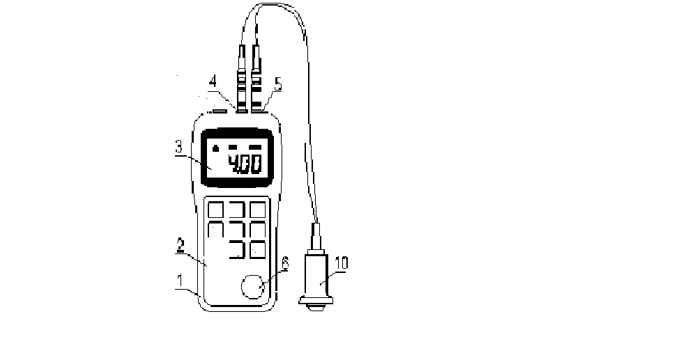
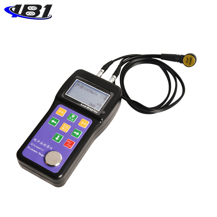
1 housing 2 keyboard 3 LCD screen 4 transmitting socket 5 receiving socket
6 Calibration thickness block 10 Ultrasound probe (probe for short)
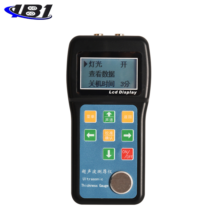
After the instrument is turned on, it will automatically enter the main display interface, as shown in the figure below:
Coupling state: the coupling state between the probe and the workpiece
Unit system: MM, M / S (in the metric system)
Battery level: remaining battery level display
Information display: display thickness measurement value and simple operation prompt information.
|
|
Instrument key |
|
menu |
|
|
Number increase key / Up key / Frequently used sound speed switch key |
Cancel key / Sound speed and thickness measurement mode switching key |
|
|
Calibration key / Enter key |
|||
|
Digit selection key |
Numeric Decrease / Down / Data Save |
3 Preparation before measurement
Please refer to the packing list to check the instrument and accessories carefully when you purchase a new instrument, please contact the manufacturer in time if it is incomplete
Select the probe according to the thickness and shape of the measured object.
For the selection basis, please refer to Table 1.2: Probe Selection in 1.4 of this manual.
3.3 Surface treatment of the tested workpiece
If the surface of the test object is rough or severely rusted, please use the following methods:
Use coupling agent on the surface of the test object;
Use rust remover, wire brush or sandpaper to treat the surface of the test object
Multiple measurements near the same point
4.1 Switching the instrument on and off
1) Insert the probe plug into the instrument probe socket;
2) Press Key, the instrument screen automatically enters the measurement interface after displaying the startup screen, and displays the sound velocity value set in the current instrument. At this time, the parameters of the instrument are the parameters used before the last shutdown.
In the on state, pressThe key can realize shutdown operation.
Probe calibration should be performed every time the probe is changed, the speed of sound is changed, the battery is changed, the ambient temperature changes greatly, or the measurement is deviated. This step is critical to ensuring measurement accuracy. Repeat as many times as necessary. Proceed as follows:
1) Standard test block provided on the measuring instrument ((4.00 ± 0.01) mm, when the speed of sound is 5920m / s);
2) The instrument displays the calibration measurement value ((4.00 ± 0.01) mm, when the sound velocity is 5920m / s), and the calibration process is complete.
note!
(1) Before the calibration operation, please confirm whether you have exited the sound speed modification mode. The instrument cannot perform the calibration operation in the sound speed modification mode.
(2) It is only limited to couple the probe to the standard test block on the instrument panel for calibration. Do not use this key on any other test block, otherwise it will cause measurement error.
When the sound speed of the material is known, the sound speed adjustment function provided by the instrument can be used, and the built-in sound speed value of the instrument can be adjusted according to the reference sound speed value in the attached table. The operation method is:
Way 1
(1) In the thickness measurement mode, press the key, or press the key to enter the sound speed adjustment.
(2) Press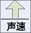 Key, or press the key to modify the sound velocity value;
(3) Please exit the sound speed modification mode after modifying the sound speed value
Way 2
(1) Press the key directly in the thickness measurement mode and select the common speed of sound
When the sound velocity of the measured material is unknown, the sound velocity measurement function provided by the instrument can be used to calculate the sound velocity value of the material. Please note that when using this function, the user is requested to use a test block of the same thickness and known thickness as the tested material. The specific operation process is as follows:
1) First perform a zero calibration of the probe (the probe cannot enter the speed measurement mode without calibration)
2) In thickness measurement mode, press the key to switch to sound speed measurement mode;
3) In the sound velocity measurement mode, press the key, or press the key to enter the workpiece thickness adjustment;
4) PressKey, or press the key to modify the workpiece thickness value.
5) Press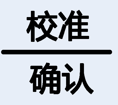 Key to confirm the sound speed of the workpiece and automatically return to the thickness measurement mode.
Apply the couplant evenly to the measured area, tightly couple the probe to the surface of the measured material, and the screen will display the measured thickness of the measured area. When the probe is well coupled with the measured material, the screen will display the coupling mark. If the coupling mark flashes or there is no coupling mark, it indicates that the coupling condition is not good. When the probe is removed, the coupling mark disappears and the thickness value remains.
4.6.1 Store measurement
1) Up to 40 thickness measurements in the instrument. After the thickness measurement, you can directly press the key to save the measurement value into the current file; if you want to view the thickness value, you can view it in the menu as follows:
2) In the thickness measurement state, press the key to enter the menu;
3) Press the key to select the view data option.
4) Press to view the thickness measurement data saved before.
5) PressKey, or press key to view 40 thickness measurement values.
When the thickness value is stored, if the total number of records in the current file has reached 40, the instrument will automatically save the thickness measurement data cyclically.
The LCD screen of the instrument is equipped with EL backlight function, so that the measurement value can be read in the dark place. Since the power consumption of the instrument increases significantly after the backlight is turned on, please turn on the backlight only when necessary to save power and extend battery life.
In the thickness measurement state, press the key to enter the menu to set the backlight switch.
The main body of the instrument is equipped with two AA size (size 5) alkaline batteries connected in series. When the battery is fully charged, the battery indicator will be displayed full. After the battery has been used for a period of time, the battery symbol will be displayed as non-full. When the battery is almost exhausted, the battery symbol will flash At this time, the battery should be replaced immediately.
The instrument has an automatic shutdown function to save battery power.
There are automatic shutdown settings in the menu options
0 is divided to turn off the automatic shutdown function;
3 points: The instrument will automatically shut down after 3 minutes when there is no operation and no object is detected;
6 points: The instrument will automatically shut down after 6 minutes when there is no operation and no object is detected;
9 points: The instrument will automatically shut down after 9 minutes when there is no operation and no object is detected;
When the battery voltage is too low, the instrument will automatically shut down.
5 Measurement application technology
Single-point measurement method: At any point on the measured object, use the probe to measure, and the displayed value is the thickness value.
Two-point measurement method: Use the probe to perform a second measurement at the same point of the measured object. In the second measurement, the split surface of the probe is 90º, and the smaller value is the thickness value.
Multi-point measurement method: Perform multiple measurements in a circle with a diameter of about 30 mm, and take the minimum value as the thickness value.
Continuous measurement method: Single-point measurement method is used to continuously measure along the specified line, and the interval is not less than 5 mm.
5.2 Pipe wall measurement method
When measuring, the probe split surface can be measured along the axis of the pipe or the axis of the vertical pipe. If the pipe diameter is large, the measurement should be made in the direction of the vertical axis; when the pipe diameter is small, it should be measured in the two directions, and the minimum value is taken as the thickness value.
When the battery capacity is nearly exhausted or exhausted, the battery should be replaced in time to avoid affecting the measurement accuracy. When the instrument is not in use for a long time, remove the battery to prevent battery leakage and corrosion of the instrument case and electrode pads.
Pay attention to the positive and negative polarities when installing the battery! Reversed polarity may cause damage to the instrument!
Avoid strong vibration of the instrument and probe;
Avoid placing the instrument in too humid environment;
When inserting or removing the probe, you should hold the movable jacket firmly along the axis. Do not rotate the probe to avoid damaging the probe cable core wire.
The adhesion of oil and dust will gradually deteriorate and break the probe wire. After use, the dirt on the cable should be removed.
6.3 Precautions during measurement
When measuring, only when the coupling icon appears and is stable, it is a good measurement;
If there is a large amount of couplant on the surface of the test object, when the probe leaves the surface of the test object, the couplant will cause mismeasurement. Therefore, at the end of the measurement, the probe should be quickly removed from the surface of the test object.
The surface of the probe is acrylic resin, which is sensitive to redrawing of rough surfaces, so it should be pressed lightly during use; when measuring rough surfaces, try to reduce the stroke of the probe on the work surface.
During normal temperature measurement, the surface of the measured object should not exceed 60 ° C, otherwise the probe cannot be used again.
If the probe is worn, the measured value will be unstable. In this case, replace the probe.
6.4 Cleaning of standard test blocks
Coupling agent is required when calibrating the instrument with a standard test block, so please pay attention to the rust prevention of the test block. Wipe off standard test blocks after use. Do not get sweat when the temperature is high. If not used for a long time, you should apply a little grease on the surface of the random test block to prevent rust. When you use it again, wipe the grease to work normally.
Alcohol, diluent, etc. have a corrosive effect on the cabinet, especially the window, so when cleaning, gently wipe with a small amount of water.
When the instrument is abnormal (such as the instrument is damaged and cannot be measured; the liquid crystal display is abnormal; the error is too large during normal use; the keyboard operation fails or is confusing), please do not disassemble or adjust any fixed assembly parts After completing the warranty card, it will be sent to our maintenance department to implement the warranty regulations.
7 Storage and transportation conditions
Store away from vibration, strong magnetic fields, corrosive media, humidity, and dust, and store at room temperature.
The transportation can be carried out under the condition of the third-grade highway while keeping the original packaging.
|
material |
Speed of sound |
||
|
in / µs |
m / s |
||
|
铝 |
Aluminum |
0.250 |
6340-6400 |
|
钢 |
Steel, common |
0.233 |
5920 |
|
stainless steel |
Steel, stainless |
0.226 |
5740 |
|
brass |
Brass |
0.173 |
4399 |
|
铜 |
Copper |
0.186 |
4720 |
|
铁 |
Iron |
0.233 |
5930 |
|
cast iron |
Cast iron |
0.173-0.229 |
4400-5820 |
|
铅 |
Lead |
0.094 |
2400 |
|
nylon |
Nylon |
0.105 |
2680 |
|
银 |
Silver |
0.142 |
3607 |
|
金 |
Gold |
0.128 |
3251 |
|
锌 |
Zinc |
0.164 |
4170 |
|
钛 |
Titanium |
0.236 |
5990 |
|
锡 |
Tin |
0.117 |
2960 |
|
Acrylic resin |
0.109 |
2760 |
|
|
Epoxy resin |
Epoxy resin |
0.100 |
2540 |
|
冰 |
Ice |
0.157 |
3988 |
|
镍 |
Nickel |
0.222 |
5639 |
|
Plexiglas |
Plexiglass |
0.106 |
2692 |
|
ceramics |
Porcelain |
0.230 |
5842 |
|
PVC |
PVC |
0.094 |
2388 |
|
quartz |
Quartz glass |
0.222 |
5639 |
|
Vulcanized rubber |
Rubber, vulcanized |
0.091 |
2311 |
|
水 |
Water |
0.058 |
1473 |
Appendix A Material Sound Velocity
Note: The sound speeds listed are approximate and are for reference only.
Appendix B Common Problems and Solutions in Ultrasonic Thickness Measurement
B.1 Influence of surface condition on measurement results
B.1.1 Surface covering
Before the measurement, all dust, dirt and rust on the surface of the measured object should be removed, and coverings such as paint should be removed.
B.1.2 Rough surface
An excessively rough surface can cause measurement errors or even no readings from the instrument. The surface of the material to be measured should be as smooth as possible before measurement, and it can be smoothed by grinding, polishing, filing, etc. High viscosity coupling agents can also be used.
B.1.3 Rough surface
Regular fine grooves caused by rough machining surfaces (such as lathes or planers) can also cause measurement errors. The processing method is the same as above. In addition, adjust the angle between the ultrasonic probe crosstalk interlayer plate (thin metal layer passing through the center of the bottom surface of the probe) and the thin groove of the measured material so that the interlayer plate and the narrow groove are perpendicular or parallel to each other, and take the minimum value of the reading As a measure of thickness, better results can be obtained.
B1.4 Cylindrical surface
For measuring cylindrical materials, such as pipes and oil drums, it is important to properly select the angle between the probe crosstalk insulation plate and the axis of the material being measured. Simply put, the probe is coupled to the measured material, the probe crosstalk barrier is parallel or perpendicular to the measured material axis, and the probe is slowly shaken perpendicularly to the measured material axis. The reading on the screen will change regularly. Select the lowest of the readings as the measured thickness of the material.
According to the curvature of the material, the angle between the probe crosstalk insulation plate and the axis of the material to be measured is correctly selected. For larger diameter pipes, select the probe crosstalk insulation board perpendicular to the pipe axis; for smaller diameter pipes, choose two measurement methods, parallel and perpendicular to the pipe axis, and take the minimum value of the reading as the measurement thickness.
B1.5 Compound Shape
The above method can be used when measuring materials with a composite shape (such as at the elbow of a pipe). The difference is that a second measurement is performed, and the two values of the probe crosstalk insulation plate perpendicular to and parallel to the axis are read. , Its smaller number is used as the thickness measurement value of the material at the measurement point.
B1.6 Non-parallel surfaces
In order to obtain a stable and reliable thickness measurement value, the other surface of the measured material must be parallel or coaxial with the measured surface, otherwise it will cause a large measurement error or no reading display at all.
B.2 Influence of temperature on measurement results
Both the thickness of the material and the propagation speed of the ultrasonic wave in the material are affected by temperature. When high measurement accuracy is required, the test block comparison method can be used, that is, the test block with the same material and approximate thickness is used to measure at the same temperature condition, and the temperature compensation coefficient is obtained. This coefficient is used to correct the measured value of the workpiece
B.3 Influence of material attenuation on measurement results
For some materials such as fiber, porous, coarse crystal, etc., they will cause a lot of ultrasonic scattering and energy attenuation, so that the instrument may have abnormal readings or even no readings (usually the abnormal reading is less than the actual thickness). In this case, the material is not suitable for thickness measurement with this thickness gauge.
B.4 Use of reference test blocks
Accurate measurement of different materials under different conditions. The closer the material of the calibration test block is to the measured material, the more accurate the measurement. The ideal reference test block will be a set of test materials with different thicknesses. The test block can provide instrument compensation correction factors (such as the material's microstructure, heat treatment conditions, particle direction, surface roughness, etc.). In order to meet the requirements of maximum accuracy measurement, a set of reference test blocks will be important.
In most cases, only a reference test block can be used to obtain satisfactory measurement accuracy. This test block should have the same material and similar thickness as the measured material. Take a uniform test material and use a micrometer to measure it, then it can be used as a test block.
For thin materials, when its thickness is close to the lower limit of the probe measurement, a test block can be used to determine the accurate lower limit. Do not measure material below the lower limit thickness. If a range of thicknesses can be estimated, the upper limit of the thickness of the test block should be selected.
When the material to be measured is thick, especially alloys with complicated internal structures, etc., a group close to the material to be measured should be selected in a set of test blocks to facilitate the calibration.
The internal structure of most forgings and castings has directionality. In different directions, the speed of sound will change slightly. In order to solve this problem, the test block should have the internal structure in the same direction as the material being tested. The direction of propagation must also be the same as in the material under test.
Under certain circumstances, the sound velocity meter of known materials can be used instead of the reference test block, but this is only an approximate replacement of some reference test blocks. In some cases, the value in the sound velocity meter is different from the actual measurement. This is because of the material. Physical and chemical conditions are different. This method is often used to measure low carbon steel, but it can only be used as a rough measurement.
The thickness gauge has the function of measuring the speed of sound, so it can measure the speed of sound first, and then measure the workpiece with the speed of sound.
B.5 Casting measurement
Casting measurement has its particularity. The grains of the casting material are relatively coarse, and the structure is not dense enough. In addition, the measurement is often made on the rough surface, so the measurement encounters greater difficulties.
The first is the large attenuation of acoustic energy caused by the coarseness of the grains and the denseness of the structure. The attenuation is caused by the scattering and absorption of acoustic energy by the material. The degree of attenuation is closely related to the grain size and the ultrasonic frequency. At the same frequency, the attenuation increases with the increase of the grain diameter, but there is a highest point. Above this point, the grain diameter increases again, and the attenuation is basically the same. To a fixed value. For probes with different frequencies, the attenuation increases with increasing frequency.
Secondly, when the grains are coarse and there is a coarse heterogeneous structure in the casting, abnormal reflection of the ultrasonic signal will be generated, resulting in grass-like echoes or tree-like echoes, which will cause incorrect readings of the thickness measurement results and cause misjudgment.
In addition, as the crystal grains become larger, the anisotropy in the direction of metal crystallization becomes more pronounced, which causes a difference in sound velocity in different directions, with a maximum difference of even 5.5%. In addition, the compactness of the tissues at different positions in the workpiece is also inconsistent, which will also cause differences in the speed of sound. These factors will cause inaccurate measurement results. Therefore, special care must be taken when measuring castings.
Attention should be paid to the measurement of castings:
When measuring castings with rough surface, you must use a relatively viscous motor oil, butter, etc. as the coupling agent.
It is recommended to use the same material as the test object, and the test direction is the same as the test object to calibrate the sound velocity of the material.
Two-point calibration can be performed if necessary.
B.6 Methods to reduce measurement errors
B.6.1 Ultra-thin materials
Using any ultrasonic thickness gauge, when the thickness of the measured material falls below the lower limit of the probe, it will cause measurement errors. If necessary, the minimum limit thickness can be measured by the test block comparison method.
When measuring ultra-thin materials, an erroneous result called \"double refraction \" sometimes occurs. The phenomenon is: the display reading is twice the actual thickness; another erroneous result is called a\"pulse package The phenomenon that the measured value is larger than the actual thickness. To prevent this kind of error, repeated measurement and check should be performed when measuring critical thin materials.
B.6.2 Rust spots, corrosion pits, etc.
The rust spots on the other surface of the tested material (small rust spots are sometimes difficult to find) will cause the readings to change irregularly, and in extreme cases even no readings. When pits are found or you are skeptical, you need to be very careful in measuring this area, and you can choose different positions of the probe crosstalk partition board for multiple tests.
B6.3 Material identification error
When the instrument is calibrated with one material and another material is measured, incorrect results will occur. Care should be taken to select the correct sound velocity.
B6.4 Probe wear
The surface of the probe is acrylic resin. Long-term use will increase its roughness and reduce the sensitivity of the probe. If the probe wears severely and causes a large error in the measurement result, the surface of the probe can be polished with sandpaper or oil stone to smooth it and ensure parallelism. If the measured value is still unstable, the probe needs to be replaced.
B6.5 Multi-layer materials and composite materials
It is not possible to measure multi-layer materials with tightly bonded surfaces, as ultrasonic waves cannot penetrate uncoupled bonded surfaces. Because ultrasonic waves cannot propagate at a uniform speed in composite materials, instruments that measure thickness using the principle of ultrasonic reflection are not suitable for measuring multilayer materials and composite materials.
B6.6 Influence of oxide layer on metal surface
Some metals may produce a denser oxide layer on the surface, such as aluminum. This oxide layer is tightly bonded to the substrate without an obvious interface. However, the propagation speed of ultrasonic waves in these two materials is different, which will cause measurement. Error, and the size of the error varies with the thickness of the oxide layer. Please pay attention to this situation when using. You can select a piece from the same batch of measured materials to make a sample, measure its thickness with a micrometer or caliper, and use the sample to calibrate the instrument.
B6.7 Abnormal thickness readings
The operator should have the ability to discern abnormal readings. Usually rust spots, corrosion pits, and internal defects in the tested material will cause abnormal readings. The solution can refer to the relevant chapters of this manual.
B6.8 Selection and use of couplant
The couplant is used as a carrier for transmitting ultrasonic signals between the probe and the material under test. If the type or use of the coupling agent is improper, it may cause large errors, or the coupling mark will flicker, and the measured value will not be stable. The coupling agent should be used in an appropriate amount and spread evenly.
Choosing the right type of couplant is very important. When used on smooth material surfaces, low-viscosity coupling agents can be used (such as randomly configured coupling agents, light motor oil, etc.); when used on rough material surfaces, or vertical and top surfaces, couplings with higher viscosity need to be used Agent (such as glycerin cream, butter, grease, etc.).
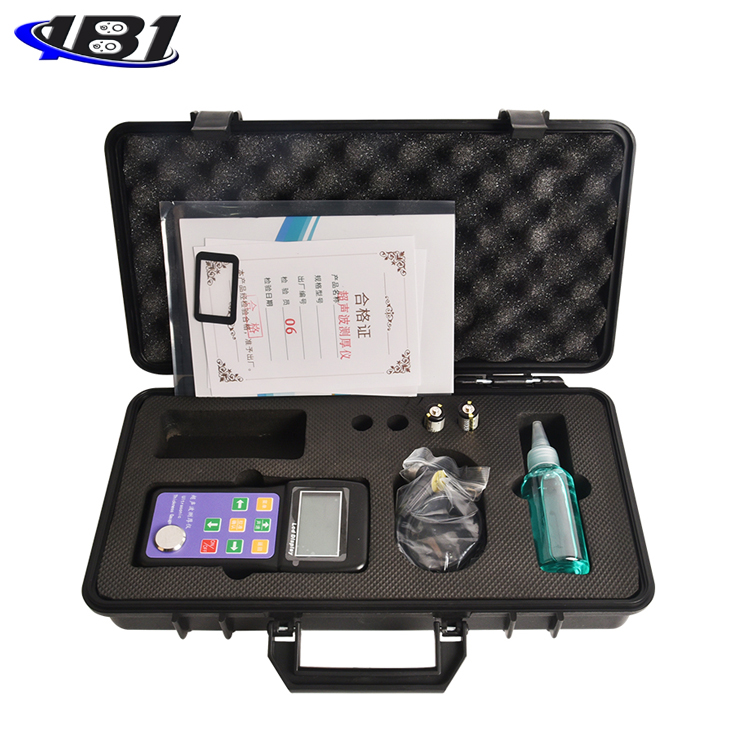
Instrument Configuration Checklist
|
Serial number |
name |
Quantity |
Note |
|
|
The standard configuration |
1 |
Host |
1 set |
|
|
2 |
Standard probe (5MHz) |
1 |
||
|
3 |
Coupling agent |
1 bottle |
||
|
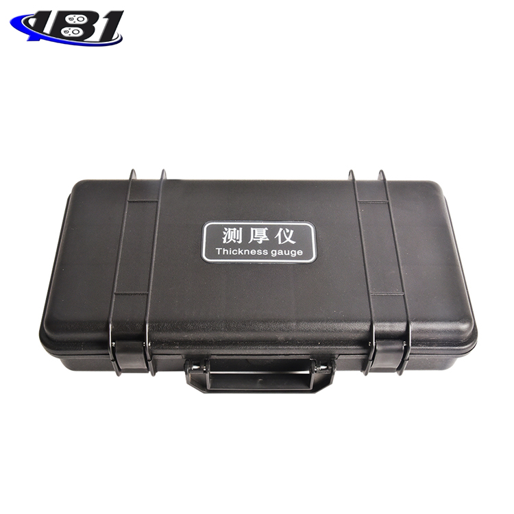
4 |
ABS instrument case |
1 |
||
|
5 |
Random data |
1 serving |
||
|
6 |
AA (size 5) alkaline batteries |
2 only |
||
|
7 |
||||
|
8 |
||||
|
Optional |
9 |
Coarse crystal probe (2MHz) |
||
|
10 |
Large-scale coarse-grained probe (2.5MHz) |
|||
|
11 |
Micro-diameter probe (7MHz) |
|||
|
12 |
Micro-diameter probe (10MHz) |
|||
|
13 |
High temperature probe (2MHz) |
|||
Notice to users
I. After the user purchases the company's products, please fill out the\"Warranty Registration Card\" carefully, and send the\"Warranty Registration Card\" stamped with the official seal of the user unit and the copy of the purchase instrument invoice to the customer service center of the company, or you can entrust sales Unit to send. When the procedure is incomplete, it can only be repaired without warranty.
2. The quality of our company's products (with the exception of non-warranty parts) within one year from the date of purchase by the user, please contact the company's instrument service department with a \"warranty card \" or a copy of the purchase invoice for free maintenance. During the warranty period, you cannot show the warranty card or a copy of the purchase invoice. The company calculates the warranty period based on the factory date, and the period is two years.
3. If the product of the company that has exceeded the warranty period fails, it can be repaired by the instrument service department of the company, and the maintenance fee will be charged according to the company's regulations.
4.\"Special configuration\" (non-standard sensors, extension cables, special software, etc.) outside the company's stereotyped products will be charged according to relevant standards.
Fifth, the company cannot dispose of the company's products by itself, damage to the product due to improper transportation, storage or incorrect operation according to the product instructions, and alter the warranty card without authorization. Without the proof of purchase, the company cannot provide warranty.
Six, please follow the instructions for correct use, if found abnormal, please stop using and contact our company