support hotline
0577-57572522


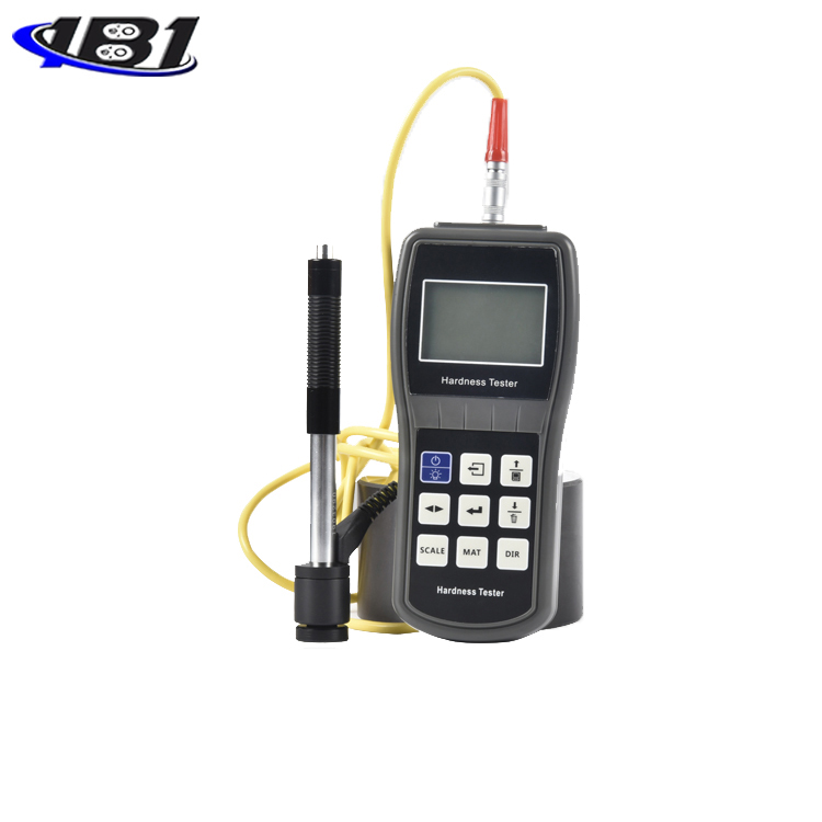
Leeb hardness tester
user's manual
Foreword
Dear user, thank you for purchasing the Leeb hardness tester (hereinafter referred to as \"hardness tester \") produced by our company. This hardness tester is a portable testing instrument with a data processing system structure. Carry and other characteristics. Before you start using this instrument, please be sure to read this \"Operating Manual \" in detail, it will provide you with the necessary help for the correct use of this instrument, hoping to make you satisfied.
This series of hardness testers meet the following standards:
\"Technical Conditions for Leeb Hardness Tester\" JB / T 9378-2001
`` Conversion relationship between hardness values of metallic materials '' ISO 18265: 2003
table of Contents
Foreword ……………………………………………………………………………… 1
Table of Contents …………………………………………………………………………………… 2
1 Name of each part of the hardness tester …………………………………………………… .. 4
2Hardness tester performance and application ………………………………………………………… 9
3 Principles of the Leeb Hardness Test …………………………………………………… 16
4 Pretreatment of test specimens ... ……………………………………………………………… 18
5 Use and operation ... ……………………………………………………………… 24
6 Maintenance ………………………………………………………………………… 47
7 Several problems affecting the accuracy of the test ………………………………………………………… 48
8 Fault Analysis and Maintenance ………………………………………………………… .. 54
9 List of non-warranty parts ………………………………………………………… .. 58
10 \"Standard Richter Hardness Block \" Instructions for use …………………………………… ..... 58
Notice to users …………………………………………………………………………………… 61
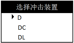
1.% 2 D type impact device
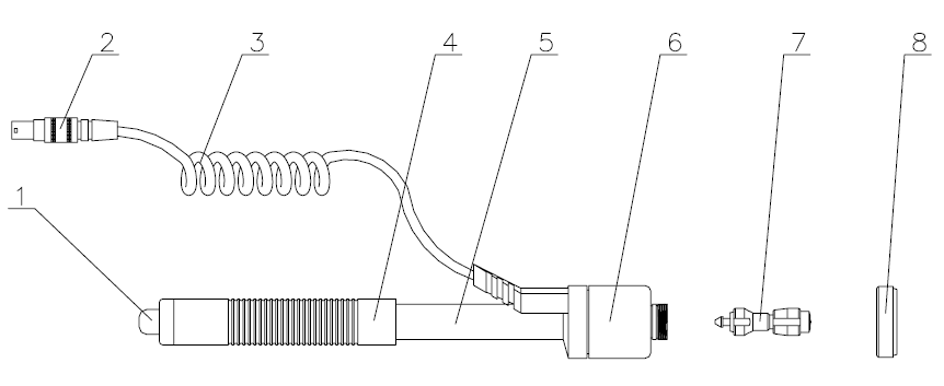
1. release button 2. impact device plug 3. lead 4. loading sleeve
5. Catheter 6. Coil part 7. Impact body part 8. Support ring
2.% 2 Optional other impact devices
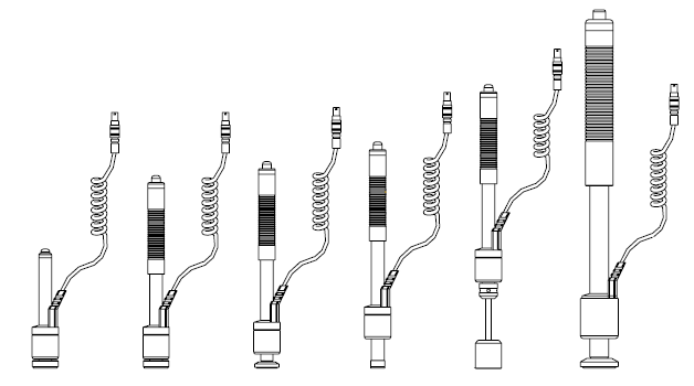
DC C E D + 15 DL G
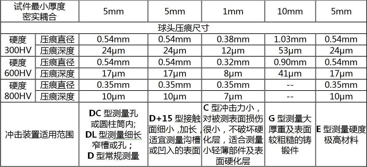
1.4 Technical parameters of impact device
Table 1: Summary of technical parameters of impact device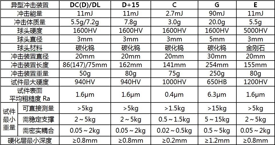
3 Hardness Tester Performance and Application
3.1 Product Features
The hardness tester is an advanced portable hardness tester, which is easy to carry, has high test accuracy, wide measurement range, convenient operation, and is suitable for all common metals. Therefore, it can be widely used in various industries such as petroleum, chemical industry, machinery and electronics.
Instrument Features:
1) Ultra-thin housing
2) Adapt to various impact devices and 6 kinds of hardness standards conversion
3) Large and clear digital display
4) Replaceable AA battery
5) Optional upper computer software with perfect database function. Support data query, data storage, statistical feature display, histogram display.
3.2 Main uses
• Mechanical or permanent assembly parts that are not easy to disassemble;
• mold cavity;
• Direct measurement of large or heavy test pieces;
• Failure analysis of pressure vessels, turbo-generators and other equipment;
• Bearings and other parts production lines;
• require formal original records of test results;
• Material differentiation of metal materials warehouses;
3.3 Main technical parameters
Hardness scale: HL, HRC, HRB, HV, HB, HS
Test accuracy: HLD: ± 6, HRC: ± 1, HB: ± 4
Standard impact device: D-type impact device
Upper and lower limit setting measurement ranges: (170-960) HLD, (17.9-69.5) HRC, (19-683) HB, (80-1042) HV, (30.6-102.6) HS, (13.5-101.7) HRB
Optional impact device: D, C, DC, D + 15, DL, G
At the same time can be equipped with the number of impact devices: any
Computer interface: USB2.0
Caption: Chinese menu
Screen display: 128 × 64 dot matrix LCD with backlight and adjustable contrast
Test direction: Support 360 degrees (vertical downward, oblique downward, horizontal, oblique upward, vertical upward)
Data storage: 200 sets of test data can be stored
Measuring the maximum hardness of the workpiece: 940HV (D, DC, DL, D + 15, C-type impact device)
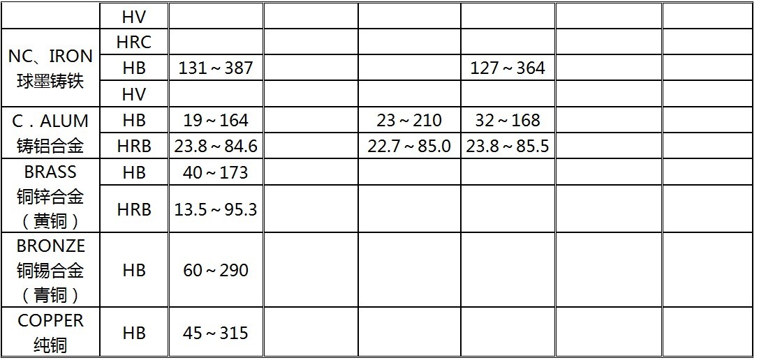
Test material quantity: steel and cast steel, alloy tool steel, gray cast iron, ductile iron, cast aluminum
Alloy, copper-zinc alloy (brass), copper-tin alloy (bronze), pure copper
Power: 1.5V dry battery
Continuous working time: about 150 hours (without backlight)
Dimensions: 155mm × 68mm × 27mm
Weight: about 230g
3.4 Main function parameters
• Select test materials, hardness standards, test directions and test times by pressing keys;
• Conversion between six hardnesses (HLD, HRB, HRC, HB, HV, HS);
• The test results can be displayed repeatedly, and the misoperation test results can be automatically or manually deleted;
• Can output the average value of a single test or all stored data at any time;
• Automatic detection of battery voltage, early warning of battery low voltage, and power display icon in test status;
• Rich status bar display, multiple statuses such as buzzer, error message, time, battery power, etc .;
• Full Chinese display, menu operation, simple and convenient operation;
• Ambient temperature: operating temperature -10 ~ + 50 ℃;
• Storage temperature: -30 ℃ ~ + 60 ℃.
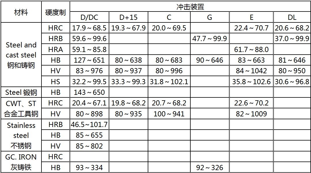
3.5 Test and conversion range
Table 2 Measurement range table
4 Leeb hardness test principle
4.1 Basic principles
With the development of single-chip microcomputer technology, Dr. Leeb, a Swiss, first proposed a new method for measuring hardness in 1978. Its basic principle is that an impact body with a certain mass impacts the surface of a specimen under a certain test force, and measures the impact body The impact speed and rebound speed at a distance of 1 mm from the sample surface use the electromagnetic principle to induce a voltage proportional to the speed. The Leeb hardness value is expressed as the ratio of the rebound speed of the impact body to the impact speed. The rebound speed of the harder material is greater than the softer one.
Calculation formula: HL = 1000 × (Vb / Va)
In the formula: HL—Rich hardness value Vb—Impact body rebound speed Va—Impact body impact speed
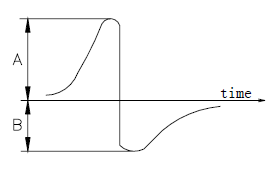
Schematic diagram of output signal of impact device
4.2 Leeb Hardness Tester
The hardness tester designed and produced according to the Leeb principle is called the Leeb hardness tester, which is used for testing the hardness of metal materials. It has the advantages of wide measurement range and arbitrary test direction.
4.3 Leeb hardness value symbol
Other hardness measurement methods have different test values when the indenter and test force (load) are changed. Similarly, when different types of impact devices are used in the Leeb hardness test, the test values cannot be substituted for each other.
That is: 720HLD ≠ 720HLG
When the Leeb value is converted into other hardness values, the conversion relationship between different impact devices is also different. Due to the different structure, the written symbols after converting other hardness values should conform to the following forms:
Example: The writing method of Shore hardness value measured by C-type impact device should be 52.8HSHLC;
The Vickers hardness value measured using D + 15 impact device should be written as 354HVHLD + 15;
The Rockwell C hardness value measured by the D-type impact device should be written as 35.9HRCHLD
5 Pretreatment of test pieces
5.1 Overview
In order to reduce the influence of the surface roughness of the test piece on the test results, the measured surface should be smooth, the surface roughness Ra value should not exceed 1.6 μm, and the surface of the test piece should be clean and free of oil.
5.2 Support and coupling of test piece during test
1) If the mass of the test piece is more than 5kg, no support is required.
2) For specimens with a mass of 2 to 5kg, overhanging specimens and thin-walled specimens, during the test, an object with a mass of more than 5kg should be used to firmly support it to prevent the impact force from causing bending and deformation of the specimen. mobile.
3) For a test piece with a mass of less than 2kg, it should be tightly coupled with a support body greater than 5kg. The coupling surface of the test piece and the surface of the support body should be flat and smooth without excess coupling agent. The test direction must be perpendicular to the coupling surface.
4) The mass of the test piece shall not be less than 0.1kg, the minimum thickness shall not be less than 5mm, and the depth of the hardened layer shall be greater than 0.8mm.
5) The clamp is clamped and shall be perpendicular to the test direction.
When the test piece is a large-area plate, a long rod, or a curved workpiece, even if the quality and thickness are large, it may still cause the test piece to change.
6) Deformation and instability result in inaccurate measurements, so the back of the test point should be reinforced or supported.
7) The magnetic properties of the test piece itself should be less than 30 Gauss.
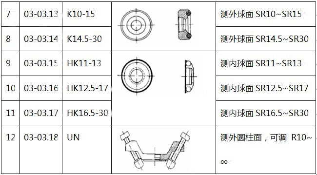
5.3 Selection of support rings when testing inner and outer cylinders and inner and outer spheres
When the curvature radius of the measured surface is less than 30mm (D, DC, D + 15, C, E, DL type impact device) and the radius of curvature is less than 50mm (G type impact device), the test piece with the random Support ring test
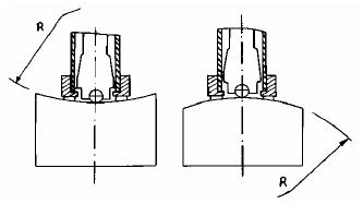
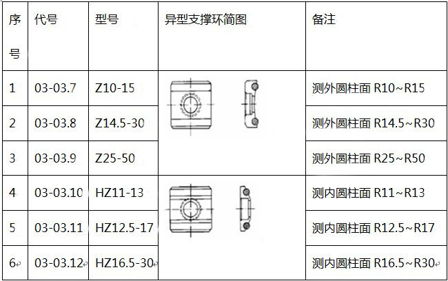
In order to facilitate the testing of various special-shaped surfaces, special-shaped support rings of our company can also be purchased separately for D, DC, D + 15, C, and E-type impact devices to obtain the best test conditions. For details, please refer to Table 3 on the next page.
6 Use and operation
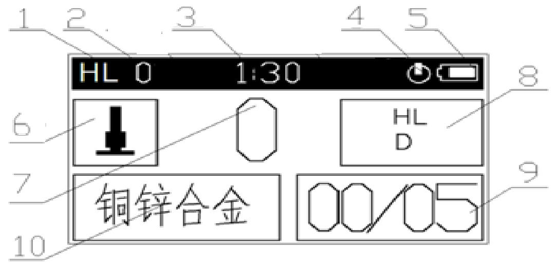
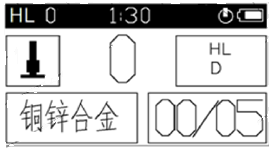
Main display interface diagram
1. Measured value Leeb unit display area 2. Original (uncorrected) Leeb measurement value 3. Time display area 4. Standby mark 5. Battery information 6. Impact direction display area
7. Measurement value display area 8. Hardness unit and impact device type display area 9. Measurement times display area 10. Measured material display area
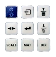
Keyboard illustration
Functions of each key:
● LCD backlight / key switch ●
 Back key to return to the previous menu or cancel the operation function
●
 Up / Save key ●
 Down / Delete
● Left and right adjustment keys ●
 Menu / Enter key
● Unit setting shortcuts ●
 Detection material setting shortcuts ●
 Detection direction setting shortcut
6.1 Power on / off
Insert the impact device's connecting wire plug into the impact device's socket first, and short press the key when the power is off., The instrument turns on and displays the following interface in turn:

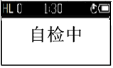
During the self-test, the instrument will automatically recognize the impact device type, and finally enter the measurement main display interface:
Press and hold the on / off key while the power is on, You can turn off the instrument.
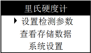
6.2 Menu structure diagram
The instrument's measurement parameter setting, system parameter setting, and saving and viewing of measurement data can be realized through menu operations. Press on the main display interfaceKey to enter the main menu-Leeb hardness tester. Press in the main menu或Key to select a menu item under the main menu, and then pressPress the key to enter the first-level submenu of the selected menu item. Under the first-level submenu, you can enter the second-level submenu in the same way. Under the second-level submenu, you can select or modify parameter settings.Press the key to confirm the setting and return. pressPress the key to return to the previous menu.
6.3 Setting detection parameters
The setting steps are as follows:
a. Press on the main display interfaceEnter the main menu-Leeb hardness tester, as shown below:
b. There are three menu items under the main menu-set detection parameters, view stored data, system settings, press或Press the key to select the\"Set test parameters\" menu item (the black triangle symbol is the check mark), pressPress the key to enter the\"\" Setting detection parameters\"\" submenu, as shown in the figure below:
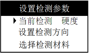
c. Press或Press the key to select a menu item in the first-level submenu.
6.3.1 Setting the measurement mode
按或Use the key to select the \"Current Testing Hardness \" first-level submenu item, pressPress the key to switch the hardness / strength measurement mode. In the intensity measurement mode, the measurement unit is the intensity unit Rm, and the intensity can only be measured with a D-type impact device.
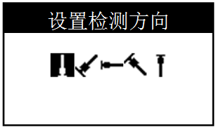
6.3.2 Setting the detection direction
按或Press the key to select the \"Set detection direction \" first-level submenu item and pressPress the key to enter the \"Set Detection Direction \" secondary submenu, pressPress the key to select the impact direction-vertical downward, 45 degrees downward, horizontal, 45 degrees upward, vertical upward, press或Press the key to confirm the setting and return to the \"Set Detection Parameters \" first-level submenu. As shown below:
6.3.3 Setting the material to be tested
As described in 5.3.2, enter the\"Select test material\" sub-menu and press或Key to select a test material, press或Press the key to confirm the setting and return to the \"Set Detection Parameters \" first-level submenu.
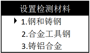
Nine materials can be measured in hardness measurement mode: steel and cast iron, alloy tool steel, cast aluminum alloy, gray cast iron, ductile cast iron, stainless steel, copper-zinc alloy, copper-tin alloy, and pure copper.
In the strength measurement mode, the following 9 materials can be measured: carbon steel, chrome steel, chrome vanadium steel, chrome nickel steel, chrome molybdenum steel, chrome nickel molybdenum steel, chrome manganese silicon steel, ultra high strength steel, and stainless steel.
Use shortcut keys to set detection materials:
This instrument has shortcut keys for setting detection materials, Press in the main measurement interfacePress the button to cyclically change the test material settings.
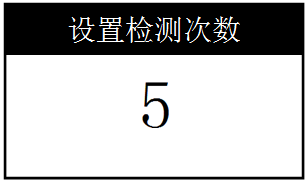
6.3.4 Set the number of detections
As described in 5.3.2, enter the \"Set Detection Times \" secondary submenu and press或Decrease or increase the number of tests, press或Press the key to confirm the setting and return to the \"Set Detection Parameters \" first-level submenu. As shown below:
6.3.5 Set detection upper / lower limit
As described in 5.3.2, enter the\"Set detection limit\" sub-menu and pressKey to select the digit, then press或Press the key to adjust the value of this digit. pressPress the key to confirm the setting and return to the \"Set Detection Parameters \" first-level submenu. As shown below:
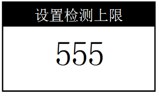
The setting of the lower detection limit is the same as the upper detection limit
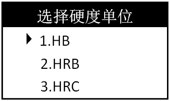
6.3.6 Setting the hardness scale
As described in 5.3.2, enter the\"Select hardness unit\" sub-menu and press或Key to select a hardness unit, press或Press the key to confirm the setting and return to the \"Set Detection Parameters \" first-level submenu. In the intensity measurement mode, the measurement unit is the intensity unit σb, and only D-type impact devices can be used to measure the intensity. As shown below:
6.3.7 Setting impact device
As described in 5.3.2, enter the\"Select Impact Device\" sub-menu and press或Press the key to select an impact device, press或Press the key to confirm the setting and return to the \"Set Detection Parameters \" first-level submenu. As shown below:
Note: In the strength measurement mode, the impact device cannot be selected, and only D-type impact devices can be used when measuring the strength.
6.4 Test
If necessary, test the instrument with a random test block if necessary.
The value of the random test block is a calibrated Leeb hardness tester, which is measured 5 times vertically downwards, and the arithmetic average value is taken as the hardness value of the random test block.
1) Loading (see Figure 1)
Push down the loading sleeve to lock the impact body.
2) Positioning (see Figure 2)
The support ring at the lower part of the impact device is pressed against the measured surface, and the distance between the two test points should be greater than 3mm.
3) Start (see Figure 3)
Test by pressing the release button on the top of the impact device. At this time, the measured workpiece, impact device and operator are required to be stable, and the force direction passes through the axis of the impact device.
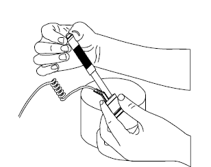
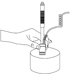
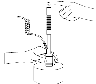
Picture one Picture two Picture three
After the end of each test, the displayed value display area shows the hardness value or strength value of the test, and the number of tests is increased by one. If the test value displays\"Ex\", it means that the test is out of range (for details, see the following description), the test is invalid. The number displayed in the test times display area does not change.
\"Ex \" symbol means detailed explanation:
\"E1 \" means there is no such test direction \"E2 \" means there is no conversion table
\"E3 \" means test value overflow \"E4 \" means test value overflow
\"E5 \" means misoperation during test
6.5 Store / view data
6.5.1 Store measurement results
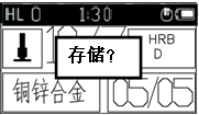
After measuring as described in 5.4, pressPress the key to store the data.Press to cancel the storageKey, as shown below:
6.5.2 Viewing Measurement Results
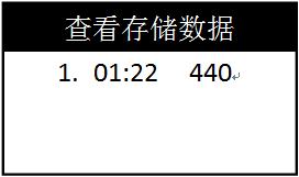
Enter the\"View storage data\" sub-menu as described in 5.3.2, press或Key to select a piece of data, pressKey to view the detailed information of the measurement results, as shown in the figure below:
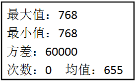
按Key to page through to see all information of stored data.
6.5.3 Delete measurement data
Enter the\"View storage data\" sub-menu as described in 5.3.2, press或Key to select a piece of data, long pressKey to delete the set of measurement data, as shown in the figure below:

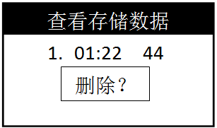
Confirm delete pressKey to cancel deletion presskey.
6.6 System settings
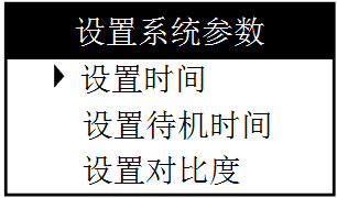
According to 5.3.2, enter the \"System Settings \" first-level submenu, as shown in the figure below:
6.6.1 Setting the date and time
按或Key to select the \"Set time \" first-level submenu item, pressPress the key to enter the \"set time \" secondary submenu, as shown in the figure below:
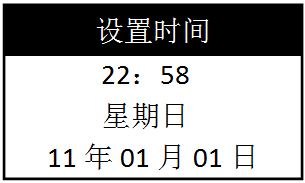
按Key to lock the date / time item to be set (blinking), then press或Press the key to change the value of the locked item. press或Press the key to confirm the setting and return to the\"System Settings\" submenu.
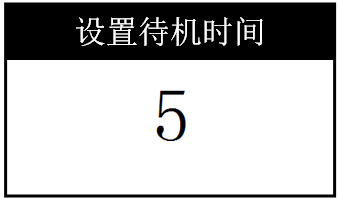
6.6.2 Setting the standby time
Set the standby time as described in 5.6.1. If the standby time is 0, the standby function is turned off. Standby time of 1 means standby for 1 second, the longest standby time is 10 seconds, after the standby time is set, the main display interface displays the standby mark 。
。
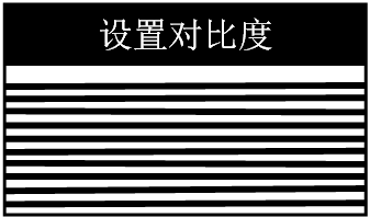
6.6.3 Setting the contrast
Set the contrast as described in 5.6.1 to change the brightness of the LCD screen. As shown below:
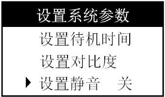
6.6.4 Set mute
Enter the\"Mute Off\" sub-menu as described in 5.6.1, pressThe key turns off / on mute, as shown below:
6.6.5 Setting the language
Refer to 5.6.4 to switch the Chinese / Chinese display of the instrument.
6.6.6 Viewing the serial number
See 5.6.4 for the serial number of the instrument.
For other settings, refer to 5.6.4.
7 Maintenance
7.1 Impact device
1) After using 1000-2000 times, use a nylon brush to clean the catheter and impact body of the impact device. When cleaning the catheter, first unscrew the support ring, then remove the impact body, and rotate the nylon brush into the tube counterclockwise After pulling it out, repeat this cleaning 5-6 times, then install the impact body and support ring.
2) After use, release the impact body.
3) The use of various lubricants in the impact device is absolutely prohibited.
7.2 Host
When the instrument power is too low, the battery should be replaced in a timely manner, as follows:
1) PressKey to shut down, open the battery compartment cover and remove the battery;
2) Put the charged No. 7 alkaline battery into the battery compartment (note the battery polarity), and close the battery compartment cover.
When the instrument is not in use for a long time, the battery should be removed to prevent battery leakage from corroding the instrument.
8 Several issues affecting test accuracy
As the Leeb hardness tester measures the hardness of metals under the action of dynamic forces, there are many factors that affect the accuracy of test results. Therefore, certain restrictions should be placed on these factors, including: test conditions, test objects, operating skills and data Several key links such as processing are discussed below on some specific issues:
1) The influence of specimen curvature on accuracy:
In the field work, we often encounter curved test pieces, and various curved surfaces have different effects on the hardness test results. Under the condition of correct operation, the instant position when the impact body falls on the surface of the test piece is the same as the flat test piece. The support ring is sufficient. However, when the curvature is small to a certain size, the elasticity difference due to the deformation of the plane conditions is significant, which will make the rebound speed of the punch lower, thereby lowering the Leeb hardness value. The punch is falling on the test piece. There is the following deviation between the surface and the plane:
For convex interview pieces, the deviation of the impact distance of the punch earlier than the planar condition at the instant of impact can be calculated according to the following formula.
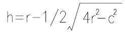
Where h — distance deviation r — curvature radius of test piece c — diameter of port in support ring
For concave curved specimens, the distance deviation can also be calculated according to the above formula, but c is changed to: outer diameter of the support ring. For large support rings (inner and outer diameters are 8mm and 19.5mm) and small support rings (inner and outer diameters are 8mm and 13.5mm respectively), the distance deviation is generally not more than 0.5mm. This requirement also applies to the remaining height of the weld. Distance deviation caused by factors.
2) Errors due to data conversion
The error when Leeb hardness is converted into other hardness includes two aspects. One is the measurement error of Leeb hardness itself. This involves the dispersion when the test is repeated in the same method and the error for multiple Leeb hardness testers of the same model. On the other hand, the error caused by comparing the hardness of different hardness test methods is due to the fact that there is no clear physical relationship between the various hardness test methods and it is affected by the unreliability of measurement in mutual comparison. The hardness conversion of this instrument is done automatically, so the Brinell, Rockwell, Vickers hardness standard blocks can be used to directly determine the conversion error of the hardness tester.
3) Errors caused by special materials
For special materials, the following methods can be used to establish the corresponding relationship.
a) Test surfaces must be prepared carefully
b) If no coupling is performed, select the largest sample size possible
c) The hardness of the sample is within the conversion range of the hardness tester
d) Check the accuracy of the static hardness tester with the hardness block of the corresponding measurement range
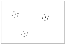
e) Measure three points on the specimen with a static hardness tester and five values with a Leeb hardness tester around the indentation and take the average. As shown below. Comparing the hardness values measured by the two methods gives the error range. A set of different hardness samples can also be used to draw the conversion curve by the above method.
For example: 3 Brinell indentations (+ in the figure) 3x5 Leeb measurements (o in the figure)
4) Error in gear detection.
In general, this Leeb hardness tester can ensure the accuracy of the gear surface detection with a modulus greater than 7, but when the gear modulus is less than 7, the test error is relatively large due to the small tooth surface. For this reason, the user The corresponding tooling can be designed according to the situation, which will help reduce errors.
5) Influence of material elasticity and plasticity
In addition to the hardness and strength, the Leeb value is also related to the elastic modulus. The hardness value is a characteristic parameter of the hardness and plasticity of the material, because the two must be measured together. In the elastic part, it is obviously affected by the E modulus first, but at the same time, the material with a lower E value has a larger L value. Various materials can be classified according to their elastic modulus, alloy type and heat treatment state.
6) Error caused by hot rolling direction
When the workpiece to be tested is formed by the hot rolling process, if the test direction is consistent with the rolling direction, the test value will be lower due to the larger elastic modulus E, so the test direction should be perpendicular to the hot rolling direction. For example: When testing the cross-section hardness of cylindrical parts, it should be tested in the radial direction (generally, the hot rolling direction of the cylindrical surface is axial)
7) Influence of other factors
a) Pay attention to the following points when testing the fittings:
i. Pay attention to the solid support of pipe fittings
ii. The test point should be close to the support point and parallel to the support force
iii. Put a proper core in the tube when the wall is thin
b) In the heat treatment process, sometimes the metal material changes (for example, after carburizing and quenching of 20Ge steel,
It changes from alloy structural steel to low alloy tool steel). In this case, care should be taken to select an appropriate metal material selection key.
c) The hardness dispersion of the workpiece itself also causes the repeatability error of the test value. The hardness distribution should be analyzed based on experience to reasonably explain the test value error.
d) Inaccurate operation methods, sample preparation, and probe configuration can cause errors. For solutions, see the previous chapters.
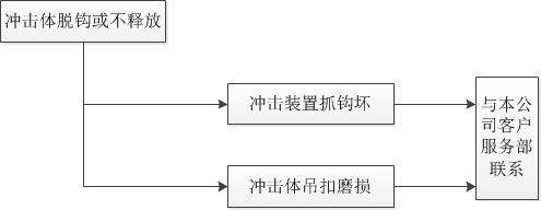
9 Failure analysis and repair
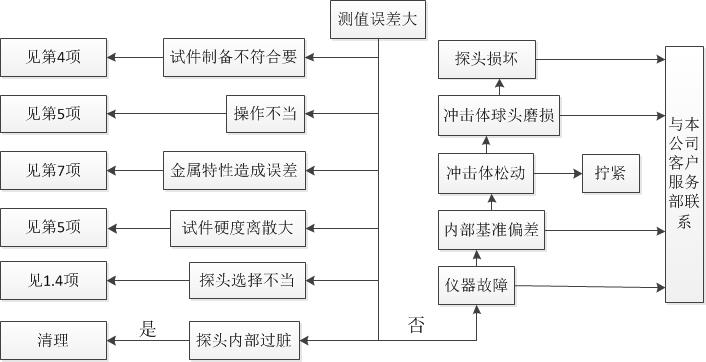
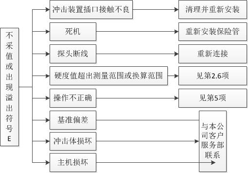
1) When the standard Rockwell hardness block is used for inspection, if the error is greater than 2HRC, the ball head may be worn out and the ball head or the impact body should be replaced.
2) When other abnormal phenomena occur in the hardness tester, please do not disassemble or adjust any fixed assembly parts. After completing the warranty card, please submit it to our maintenance department to implement the warranty regulations. The instrument stay in our company generally does not exceed one week.
10 Non-warranty parts list
1) Shell
2) Panel
3) Impact body
4) Support ring parts
5) Probe cable
6) Battery
Note: Damage caused by improper use by the user is not covered by the warranty
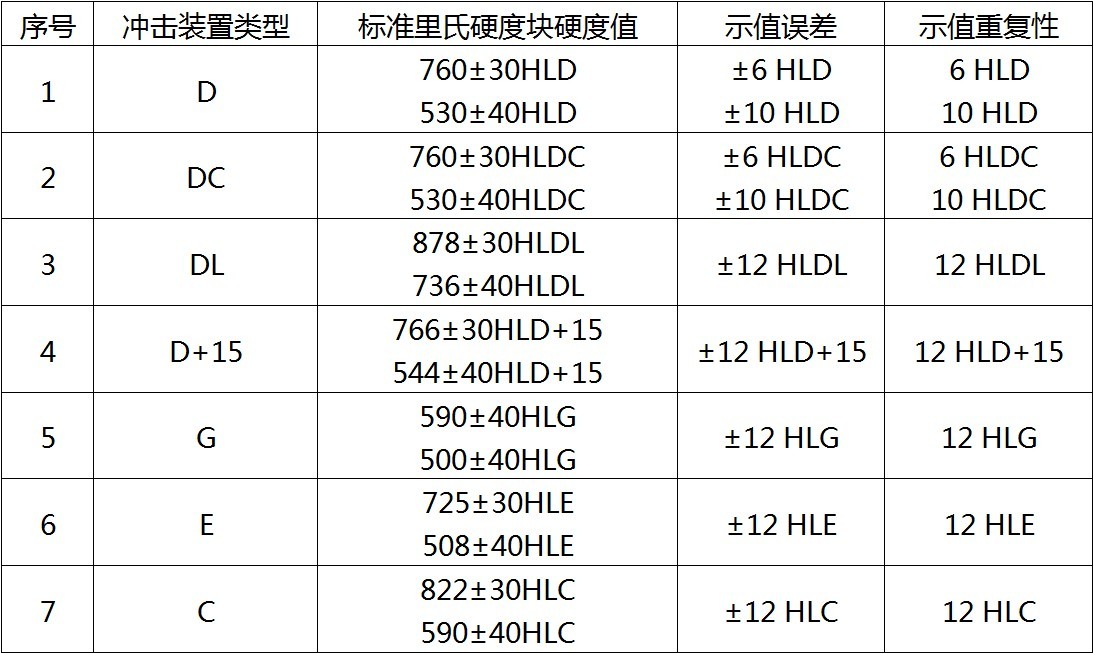
11 \"Standard Richter Hardness Block \" Instructions for use
\"Standard Leeb hardness block \" is a new standard measuring instrument for hardness measurement. It is used for the periodic and daily verification of the Leeb hardness tester. The Leeb hardness measurement value was officially transmitted from April 1, 2000. In order to let the relevant personnel of hardness measurement and testers understand and use it correctly, a brief introduction is made:\"Rich hardness tester\" National Metrological Verification Regulations (JJG747-1999) on the Leeb hardness tester's Leeb hardness indication error and repeatability The relevant requirements are listed in Table 7, which stipulates that they are applicable to newly manufactured, in use and repaired metal Leeb hardness testers.
Indication error: δ = HLD1-HLD2
In the formula: HLD1 represents the arithmetic mean value of the five-point Leeb hardness measurement value
HLD2 represents the hardness value of the standard Richter scale
Indication repeatability: b = HLDmax-HLDmin
In the formula: HLDmax represents the maximum value of 5 points Richter hardness measurement value
HLDmin represents the minimum value of 5 points Leeb hardness measurement
HLD can also be HLDC, HL (D + 15), HLC, HLG or HLE
Table 7: List of Leeb hardness tester values and repeatability errors