support hotline
0577-57572522
I. Overview
EGMM-100 is a Chinese menu gas-electricity column micrometer (hereinafter referred to as gas-electricity meter). It is a digital modular application product designed with embedded single-chip microcomputer technology. Data acquisition and digital processing of the analog signal quantity can directly display the absolute measurement value of the measured size or the relative change value from the nominal size value, that is, the relative measurement value. According to the preset workpiece size tolerance limit, it indicates whether the tested workpiece is qualified or not. It can be used as a single unit or can be cascaded together to save more operating space.
This product adopts a bright LCD display, which is especially suitable for the application of various production line environments. It has produced a Chinese menu operation interface, which greatly facilitates operation and human-computer interaction. At the same time, the LCD screen can directly display the exact value of the test result. This product can perform multi-program setting of various specifications of measured parameters, and it also has measurement data storage and query functions. (The basic model does not have this function)
The light beam of this product has three colors of red, green and orange, which indicate the measured size result and the size of its tolerance zone. You can intuitively feel the deviation of the measured size within its tolerance zone.
Preset range, nominal dimension value, tolerance band tolerance and alarm limit value, standard component dimension value; measurement directions of inner and outer dimensions can also be selected; all parameter settings have power-down saving function.
This product also has additional functions to choose: \"Peak-Peak \" measurement function; can use various mathematical models to calculate the coaxiality, ellipticity, runout, cylindricity, flatness, perpendicularity, etc. Error results; input and output signal functions can easily form a control system; data communication functions can enable multiple measuring instruments on the field to form a network, and SPC statistical charts can be formed through dedicated software to achieve on-site online quality management, etc. According to the special requirements of the user, the functions of the product can be modified and supplemented to meet the needs of different detection contents.
Product Features
Compared with the traditional analog electronic column and digital display electronic column, the Chinese screen electronic column has the following significant features and advantages.
1. Highlight the LCD screen display. Clear, no display viewing angle and lighting requirements.
2. Chinese menu operation. Intuitive, convenient and fast.
3. Three-color light bar indication
The light beam can be displayed in green, orange, and red, indicating that the measured size is \"qualified \", \"alarm \", and \"out of tolerance \" status, and it is easy to observe the position of the measured size on the tolerance zone. . There are three types of instructions: point, segment and column.
4. Digital accurate reading
At the same time as the light bar indicates, the liquid crystal display directly displays the measured precise size value, and it can display the relative and absolute values at the same time. The highest resolution can reach 0.1 μm, which is a leading position in China.
5. Can be equipped with any size gas probe
This gauge can be used for pneumatic probes with any nozzle size from Ф0.3 to Ф2.0. A measuring instrument is compatible with old-fashioned buoy pneumatic instruments.
6. Extremely high stability
A variety of anti-interference and stabilization technologies are used, which greatly improves the stability and reliability. The instrument uses a closed structure that is waterproof and oil-proof, and uses durable metal buttons. The instrument can be adapted to harsh industrial sites.
7. Ten programs can be set for various specifications
Multi-program setting of various specifications of measured parameters and storage function of measurement data can be performed. Up to ten programs can be set, corresponding to ten detection specifications. The setting parameters and calibration values of the standard parts are stored correspondingly to the program.
Facilitates multi-specification measurements.
8. Grouping function
You can set the grouping interval for grouping selection, and display the grouping number while displaying the measured value.
9. Network data management capabilities
The data communication function enables multiple measuring instruments in the field to form a measurement and control network. The upper computer management server and dedicated SPC management software collect and store measurement data to form SPC statistical charts to achieve networked online quality management.
Third, the main technical parameters and conditions of use
Specifications and main basic parameters
Model: EMM-100
|
Indication range |
Resolution (μm / 1 light tube) |
Initial clearance |
|
10 (µm) |
0.1 |
25-60 (µm) |
|
20 (µm) |
0.2 |
30-60 (µm) |
|
50 (µm) |
0.5 |
40-80 (µm) |
|
100 (µm) |
1.0 |
40-80 (µm) |
Note: For large-gap type measurement with initial gap up to about 100µm, a custom gauge is required.
2. Main basic performance
|
Display range (µm) |
± 5 |
± 10 |
± 25 |
± 50 |
|
Digital display resolution (µm) |
0.1 |
0.2 |
0.5 |
1.0 |
|
Total error of displayed value (µm) ≦ |
0.2 |
0.4 |
1.0 |
2.0 |
|
Indication value variability (µm) ≦ |
0.1 |
0.2 |
0.5 |
1.0 |
|
Dimensions |
65mm (width) X495mm (height) X180mm (depth) |
|||
|
weight |
3kg |
|||
Note: Large-scale applications with measurement ranges up to 200µm require custom gauges.
3. Conditions of use
(1) Power supply: AC185 ~ 265V 50HZ / 60HZ
(2) Power consumption: 25W
(3) Ambient temperature: 0 ~ 45 ℃
(4) Humidity: 85% or less
(5) Air source: 0.40-075MPa clean air source.
(6) Keep away from corrosive items, strong magnetic fields, strong electric fields, and strong vibrations.
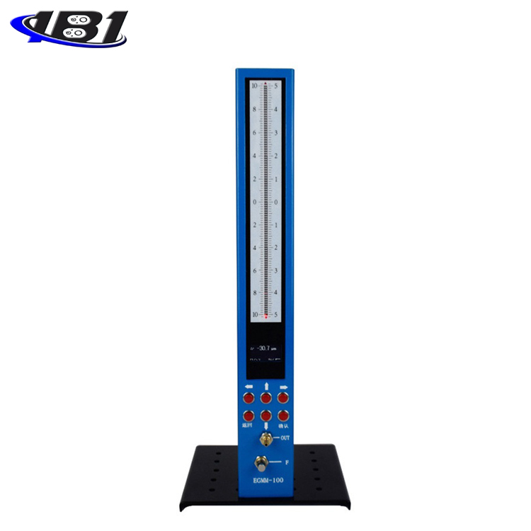
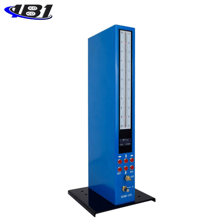
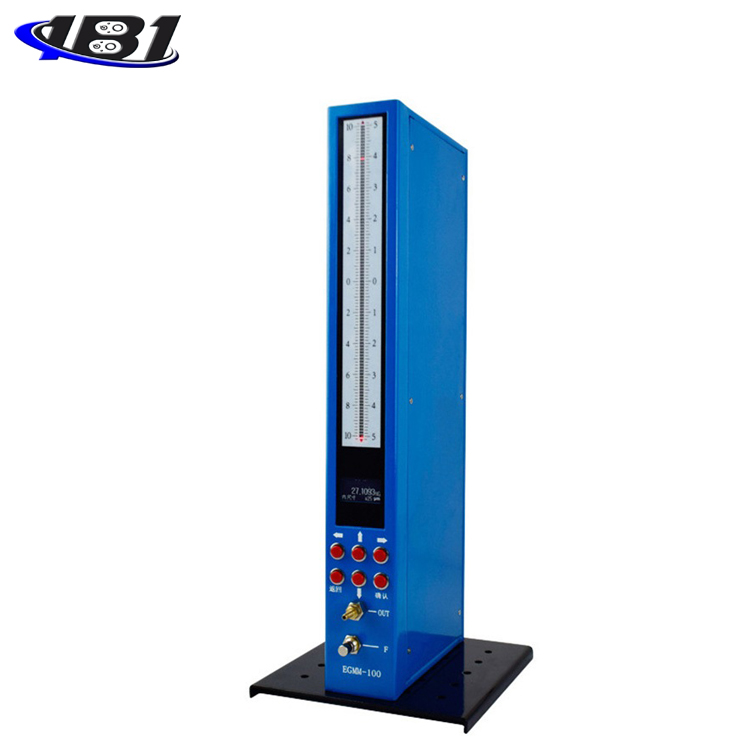
Introduction to the functions of each part of the product (as shown in Figures 1 and 2 on the right)
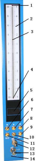
1.Forward overrange indicator
When the actual value of the sensor exceeds the positive range, the light is on.
2.Scale value indication
|
Range indication |
Range |
Light bar scale value |
|
10 |
(± 5µm) |
0.1µm / 1 lamp |
|
20 |
(± 10µm) |
0.2µm / 1 lamp |
|
50 |
(± 25µm) |
0.5µm / 1 lamp |
|
100 |
(± 50µm) |
1.0µm / 1 lamp |
3. The light beam indicator consists of 101 three-color light-emitting lamps, which are used to indicate the limit values and measured values.
When the measured value is within the range of \"Qualified\", it is displayed in green;
When the measured value is within the range of \"Alarm\", it is displayed in orange;
When the measured value is within the range of \"Out of tolerance\", it is displayed in red.
4. Negative over range indicator
When the actual value of the sensor exceeds the negative vector path, the light is on.
5. Display
Indicate the setting parameter type and value, and display the measured value in the measurement state.
6. Cursor left
7. Number increase key and cursor up key
8. Cursor right
9. Confirm
10. Number decrease key and cursor down key
11. Back key
12. Probe output quick plug connector (with Ф6 tube)
13.Magnification knob
14.Model name
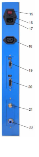
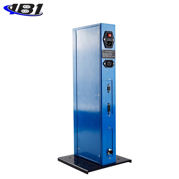
15. Power switch
16. Insurance tube
17. Power input socket
Power input, AC185 ~ 265V 50HZ / 60HZ;
18. Power output socket
Power output, AC185 ~ 265V 50HZ / 60HZ, used for multiple electronic columns.
19. Digital signal input and output interface
RS232C or RS485 / 422 interface.
20. I / O interface
External switch input signal can be used to modify the program for special purposes.
21. Silencer
22. Air source inlet quick plug connector (with Ф8 pipe)
Five, function operation instructions
Turn on the power switch on the back of the electronic column. The electronic column first enters the self-test state. The light column performs three-color conversion display. After the self-test is completed, it automatically enters the measurement function. In the measurement state, press the \"Back \" key to enter the main menu interface as shown in Figure (3), which can perform various functional operations.
When the instrument is used for the first time, it is necessary to set the system parameters. Each parameter can also be modified at any time in future use. The instrument is easy to operate. Only when the instrument is used for the first time or the gas probe is worn and needs to be replaced, the manual override function is used. The override is initially adjusted to one to one through the override knob. Mark
The standard performs precise correction of the magnification and zero position.
(I) Description of operation process
1. Initial use: ① parameter setting → ② magnification adjustment → ③ calibration of standard parts → ④ measurement
2. When the probe is replaced or the probe is worn: ① Adjustment of magnification → ② Calibration of standard parts → ③ Measurement
3. Normal use: ① Calibration of standard parts → ② Measurement
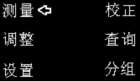
image 3)
(Two), parameter setting (press the return key after power on to return to the main menu)
1. In the main menu screen, press \"▼ \" to move the cursor to the\"Settings\" menu option on the screen. At this time, press the OK key to enter the\"Settings\" menu as shown in Figure 4
2. Press \"▲ \" or \"▲ \" key at this time to select programs No. 0-9. Press the confirmation key to select the program, and the parameters and operations set thereafter correspond to the program, and enter the next menu.
3. \"Range selection \" menu is shown in Figure (5). There are four levels of selection: ± 5µm, ± 10µm, ± 25µm, and ± 50µm.
Press \"OK \" to enter the next nominal value setting.
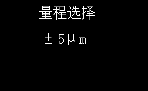
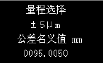
Figure (4) Figure (5)
4.\"Tolerance nominal value (ie nominal size)\" is set as shown in Figure (5), the unit is mm. Press \"◀ \", \"▶ \" keys
Move the cursor (blinking digits); press \"▲ \", \"▼ \" keys to set the value of the cursor position. The digits change between 0-9. Press \"▲ \" to increase the number, press \"▼ \" to decrease the number; press \"OK\" to enter the next item.
set up.
5. The\"upper limit\" setting is shown in Figure (6). The unit is µm. The setting method is the same as the\"tolerance value\". Symbol bit, press \"▲ \" to set positive sign \"+ \", press \"▼ \" to set negative sign \"- \"; press \"OK \" key to enter
Next setting.
6. The setting of the tolerance band\"Alarm upper limit\" is shown in Figure (6). The unit is µm. The alarm upper limit is generally equal to the upper deviation minus 1/8 of the tolerance value. The setting method is the same as the\"upper limit\". Press \"OK \" to enter the next setting. Note: If the value of this parameter is greater than the upper limit of the tolerance, you will be required to continue to set the\"Alarm Upper Limit\" and will not enter the next parameter setting until the parameter setting is correct.
7. The setting of the\"low alarm limit\" of the tolerance zone is shown in Figure (6). The unit is µm. The lower alarm limit is generally equal to the lower deviation plus the 1/8 tolerance value. The setting method is the same as the\"upper limit\". Note: If the value of this parameter is greater than the upper limit of the alarm, you will be required to continue to set the\"lower limit of the alarm\" and will not enter the next parameter setting until the parameter setting is positive.
Indeed. Press \"OK \" to enter the next setting.
8. The setting of\"low tolerance\" is shown in Figure (6). The unit is µm. The setting method is the same as the\"high tolerance\". Press \"OK \" to enter the next setting. Note: If the value of this parameter is greater than the lower alarm limit of the tolerance zone, you will be required to continue setting the lower tolerance limit and will not enter the next parameter setting until the parameter setting is correct.
9. The setting of\"upper limit standard value\" is shown in Figure (7). The unit is mm. The setting method is the same as the\"tolerance value\". Press the\"OK\" button to enter the next setting.
10. The setting of the\"lower limit standard value\" is shown in Figure (7). The unit is mm. The setting method is the same as the\"tolerance value\". Press the\"OK\" button to enter the next setting.
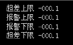

Figure (6) Figure (7)
11. \"Inner and outer size mode \" selection: Press \"▲ \", \"▼ \" keys to switch, press \"OK \" key to enter the next setting
set.
12. Set the grouping gap: the unit is μm. The measurement is performed according to the set grouping gap value. The grouping gap is positive. The grouping direction is increased by one grouping gap from the lower tolerance limit. The grouping gap is negative. The grouping direction is decreased by one grouping gap from the upper tolerance limit As a group.
13. Eyelet probe: Yes. When the probe's equivalent aperture is less than Φ0.8, select \"Yes \", other options \"No \", press \"\", \"\" key to switch. If you select\"No\" for small-hole probe measurement, the speed is too slow. If you select\"Yes\" for non-small-hole probe measurement, the measurement value is unstable.
14. Press the \"OK \" key to save the setting parameters and return to the main menu at the same time as shown in Figure (3).
15. Tolerance zone parameter setting example:
① If the measured size is 28.3920 (-0.0090, +0.0090) then: (tolerance symmetrical type)
The range should be set to: ± 10µm (because 18µm <20µm)
Nominal value: 028.3920mm.
Upper tolerance limit: + 009.0µm Alarm upper limit: + 007.0µm;
Lower alarm limit: -007.0µm Lower tolerance limit: -009.0µm
② If the measured size is 9.000 (0, + 0.0150) then: (tolerance asymmetric type)
The range should be set to: ± 10µm (because 15µm <20µm)
Nominal value: 009.0000mm
Upper tolerance limit: + 015.0µm Upper alarm limit: + 013.0µm
Lower alarm limit: + 002.0µm Lower tolerance limit: + 000.0µm
Note: At this time, the tolerance of the light beam shows an automatic symmetrical distribution (effectively using the entire length of the light beam). The light beam cannot be used for reading, but only indicates the tolerance distribution of the detection value. The relative value reading is read on the display and is relative to the nominal value of 009.0000mm. The relative value read from the light column must be added to the zero offset (zero offset = center value of the tolerance band-nominal value of the tolerance) to be the actual relative value.
③Form and position error parameters (such as runout, coaxiality, etc.)
If the tolerance is 0.05mm, it can be regarded as: 0 0 + 0.05, then: the nominal dimension value is 000.0000 is 0mm; the lower limit of tolerance: +000.0 is 0µm, the upper limit of tolerance: + 050.0µm It must be set to zero. At this time, the tolerance of the light beam shows an automatic symmetrical distribution (the entire segment of the light beam is effectively used). The light beam cannot be used for reading, but only indicates the tolerance distribution of the detection value.
(Three), magnification adjustment function
During normal use, the magnification change is very small, so you don't need to adjust it often. You need to manually adjust the magnification only in the following cases.
1) For the first time
2) When the air probe is worn
3) Replace different probes
4) When the instrument is left for a long time and then used again
In this function, the unit is µm. The upper and lower limits of the standard parts are respectively indicated by the upper and lower orange digits in the light bar. The range of the light bar range is doubled for easy debugging.
The functions of each key are as follows:
★ \"◀, \" ▶ \"keys: Release the reference point, the actual value of the probe will be displayed.
★ \"▶ \" key: Set the reference point and pull the displayed value to the lower limit of the standard part.
★ \"Back \" key: Exit the manual adjustment function.
Specific steps are as follows:
① Internal size mode:
1: Place the lower limit standard.
2: Right-click \"▶ \" to place the beam on the lower cursor position.
3: Put the upper standard part and observe the beam.
4: If the light bar indicates near the upper cursor, the adjustment is complete. If the light bar indication is not near the upper limit cursor, adjust the magnification knob. When it is insufficient, adjust to: upper limit value + insufficient amount X2. When it exceeds, adjust to: upper limit value-excess amount X2. The magnification in the clockwise direction increases; the magnification in the counterclockwise direction decreases.
5: Repeat steps 1 to 4 and repeat debugging until the light bar is near the upper limit cursor, which is generally slightly larger than the upper limit, but do not exceed the upper limit cursor 4-digit light bar. Finally tighten the locking screw to lock the override.
6: Press \"Back \" to return to the main menu.
② Outer size mode:
1: Put the upper limit standard part first.
2: Right-click \"▶ \" to place the beam on the lower cursor position.
3: Put the lower limit standard part and observe the light beam.
4: If the light bar indicates near the upper cursor, the adjustment is complete. If the light bar indication is not near the upper limit cursor, adjust the magnification knob. When it is insufficient, adjust to: upper limit value-insufficient amount X2. When it exceeds, adjust to: upper limit value + excess amount X2. The clockwise magnification increases the light beam and goes downwards; the counterclockwise magnification decreases the light beam and goes upwards.
5: Repeat steps 1 to 4 and repeat debugging until the lower limit standard light beam is placed near the lower limit cursor, and the upper limit standard light beam is placed near the upper limit cursor which is slightly larger than the upper limit cursor, but do not exceed the upper limit cursor. 4-position light beam. Finally tighten the locking screw to lock the override.
6: Press \"Back \" to return to the main menu.
(IV) Calibration function of standard parts
For gas measurement projects, the upper and lower limit standard parts are generally used to correct the magnification, and the lower limit standard part is regarded as the zero standard part. Note that the value of the standard part in the parameter setting must correspond, otherwise the measurement result will have errors, and the standard part with small size is the lower limit standard part. The unit is µm.
Specific steps are as follows:
1) In the main menu interface, as shown in Figure (3), select \"Calibration \" and press the\"OK\" key to enter the standard part calibration function.
2)\"\ Lower limit standard part\" is displayed, which means that the lower limit is calibrated first, and the lower limit standard part is placed at the measuring station.
3) At this time, if you press the \"Back \" key to exit the calibration function, no calibration will be performed.
4) After waiting for the indication value to stabilize, press the\"OK\" key to display\"OK\" and the lower limit correction is completed. Press the\"OK\" key again to enter the upper standard calibration
5) \"School upper limit standard part \" is displayed, indicating that the school has reached the upper limit, take out the lower limit standard part
6) Place the upper standard part in the measuring station.
7) After waiting for the displayed value to stabilize, press the \"OK \" key to complete the upper limit correction. After the calibration is completed, it will automatically return to the main menu interface, and you can measure after that.
Note: If the displayed value is far from the upper and lower limits during calibration, you need to adjust the magnification first. See (4), manual correction magnification function.
(V) Measurement function
Picture (8) Picture (9)
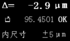
After the setting steps are completed, and coarse adjustment and calibration are performed, the measurement is entered. The measurement interface is shown in Figure (8).
First line: displays the relative value of the measurement
The second line: display the absolute value of the measurement (mm) and judgment (OK or NG)
Third line: display the measurement method and range
Press the\"OK\" key to store the measurement data. The maximum storage capacity is 800 data. The storage function can store the latest 800 measurement data. Data will not be lost after restarting. If there are more than 800 stored data, the data stored first will be overwritten sequentially. For example: When storing the 801st data, the first data will be overwritten by it. The query function allows the operator to query the 800 most recently stored measurement values. The serial number is arranged according to the storage time. The last data stored is number 1. The earlier the storage time, the larger the serial number. The data is also sent when you press the\"\" OK\"key or when the host computer vectorizer sends a\" D\"command. RS232 communication mode: baud rate 9600, 1 start bit, 8 data bits, 1 stop bit, no parity. Send data format
as follows:
1: 63.0105 NG
2: 63.0076 OK
3: 63.0063 OK
(6) Grouping function
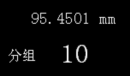
This function can be selected if group matching is needed. The group measurement interface is shown in Figure (9).
First line: Displays the absolute value of the measurement
The second line: the large word shows the grouping group number. Grouping description: grouping according to the set grouping gap value.
The grouping gap is a positive value. The grouping direction increases from the lower tolerance limit to each grouping group.
The grouping gap is negative. The grouping direction decreases from the upper limit of tolerance. Each grouping gap is reduced into a group.
(VII) Inquiry function
Figure (10)
Enter the \"Query \" interface as shown in Figure (10), which displays the workpiece serial number (1-1200), tolerance judgment (pass or out of tolerance) and stored absolute measurement value. The earlier the storage time, the larger the serial number. Power on and press the up arrow key to reset the system and clear the saved measurement value.
The functions of each key are as follows:
★ \"Back \" key: Exit the query function and enter the main menu.
★ \"▼ \" key: For downward query, the workpiece serial number increases.
★ \"▲ \" key: for upward query, the workpiece serial number decreases.
★ \"◄ \" key: Delete all stored data and return to the main menu.
Six, common failures and precautions
1) No indication when power on, please check if the power connection is normal and the fuse is normal.
2) Under the adjustment function, the upper and lower limit position indications cannot be found. It may be that the nominal size or standard part value is set incorrectly.
3) The reading is abnormally unstable and the measured value is very large. It may not be calibrated by the standard part, and it will be normal after the calibration of the standard part.
4) The power ground wire must be grounded, otherwise the instrument may work abnormally or cause personal injury. Always disconnect power before unplugging the power connector and opening the case.
5) The gas source pressure is in the range of 0.40-0.70MPa, and it is best to adjust the pressure to 0.50MPa. If the air pressure is less than 0.40MPa, the reading will be unstable.
6) The air source requires an air filter. If it is a large three-stage filter, it can take up to three gas meters; generally small air filters can only take one gas meter.
7) After adjusting the override, be sure to tighten the locking screw to lock the override, otherwise the stability of the instrument will be reduced.
8) If the magnification knob has been adjusted to the limit, the magnification is still insufficient, because the initial working gap of the probe is too large, and a higher range can be changed. If this is not possible, the probe must be replaced. It is strictly forbidden to adjust the working pressure inside the instrument, otherwise the instrument will be damaged and the warranty will not be given.
9) When the gas probe is worn for a long time, the initial clearance becomes larger. As long as the position error allows, the manual adjustment of the magnification and the calibration of the standard parts are correct and the measurement is still correct. This advantage greatly increases the service life of the gas probe.
10) When the display is abnormal, you can shut down. When you turn on the device, press and hold the up arrow key to restore the factory configuration.