support hotline
0577-57572522
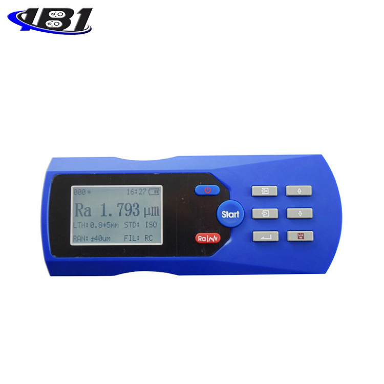
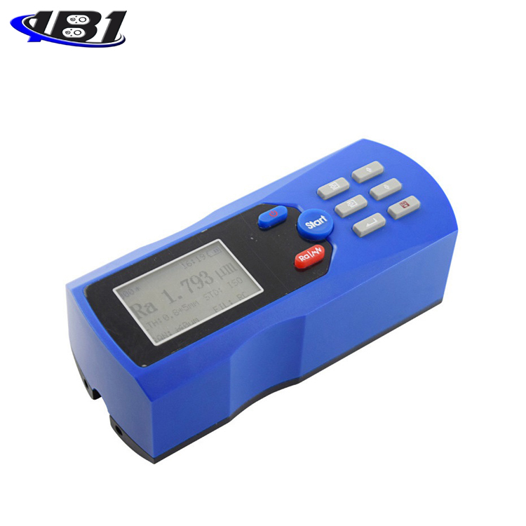

TR200 surface roughness measuring instrument is a small handheld instrument suitable for the production site environment and mobile measurement needs. It is easy to operate, comprehensive, fast, stable, and easy to carry. It can measure the main parameters of the latest international standards. The instrument strictly complies with international standards.
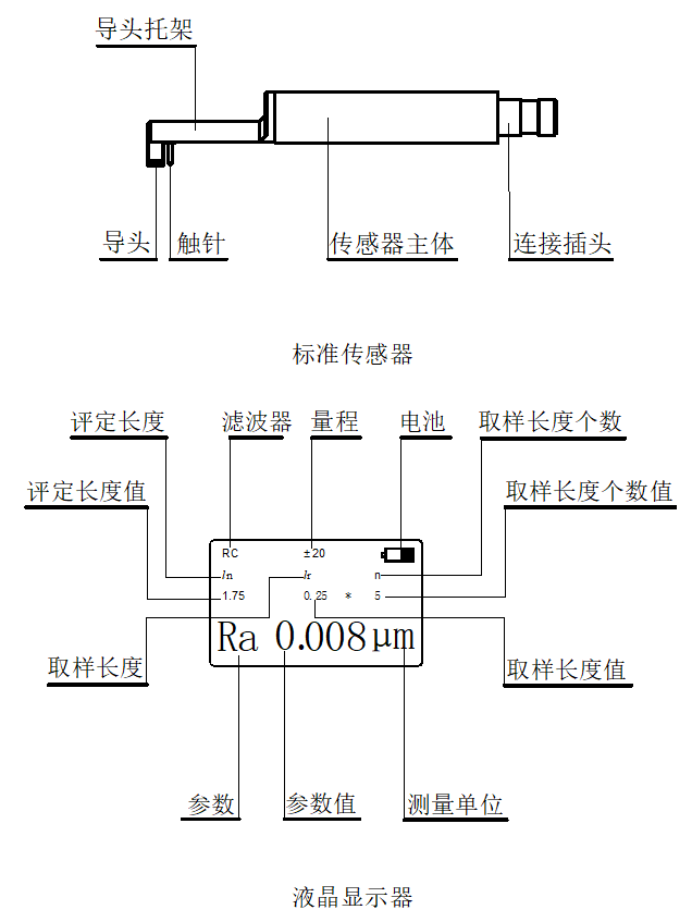
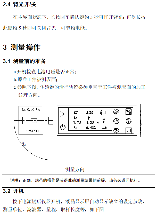
When measuring the surface roughness of the workpiece, the instrument first puts the sensor on the surface of the workpiece to be measured, and then starts the instrument for measurement. The precision driving mechanism inside the instrument drives the sensor to slide along the measured surface at a constant speed. The sharp stylus feels the roughness of the measured surface. At this time, the roughness of the measured surface of the workpiece will cause a displacement of the stylus, which will cause the inductance of the sensor's inductance coil to change. An analog signal proportional to the measured surface roughness. The signal is amplified and level converted into a data acquisition system. The DSP chip performs digital filtering and parameter calculation on the collected data. The measurement results are given on the liquid crystal display. Output on the printer, can also communicate with the PC.
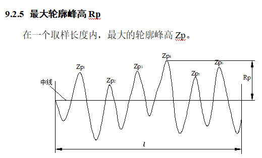
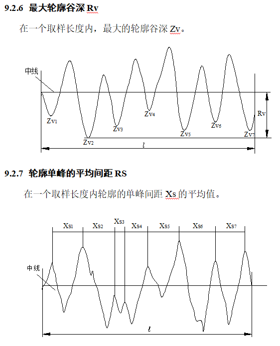
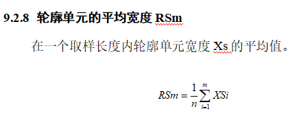
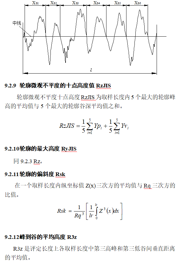
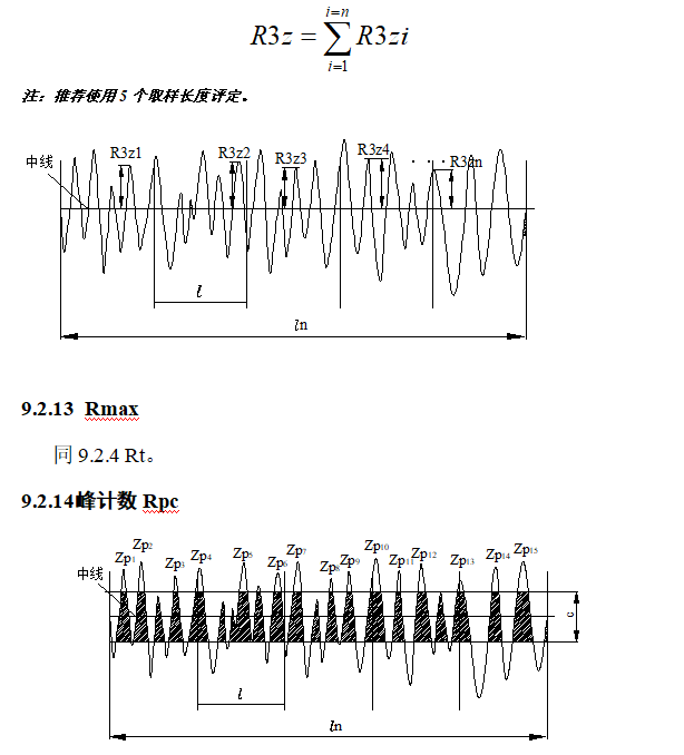
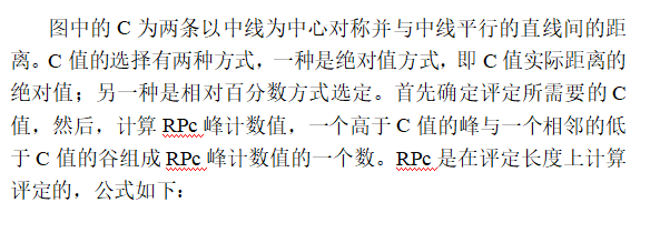
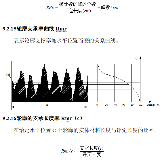
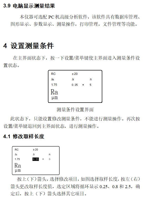
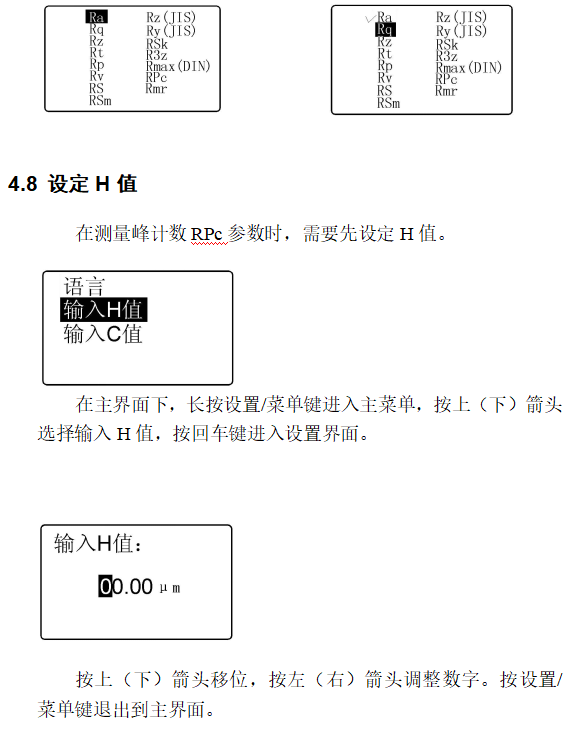
15 measurement parameters: Ra, Rq, Rz, Rt, Rp, Rv, RS, RSm, Rz (JIS), Ry (JIS), RSk, R3z, Rmax, RPc, Rmr
Using high-precision inductive sensors;
With RC, PC-RC, GAUSS, D-P four filtering methods;
Compatible with ISO, DIN, ANSI, JIS standards;
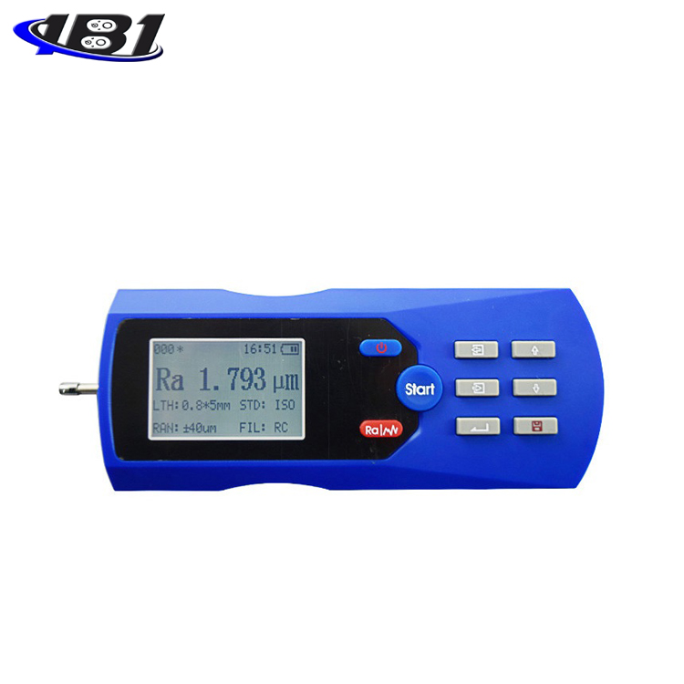
128 × 64 dot matrix LCD with backlight, which can display all parameters, outline graphics and Chinese and English menus;
Use DSP chip for control and data processing;
Built-in lithium-ion rechargeable battery and charging protection circuit;
Mechatronics design, smaller size;
Connect to a printer to print all parameters and contour graphics;
Built-in standard RS232 interface, can be converted into USB to communicate with PC;
With automatic shutdown and various operation prompt information;
Optional micro printer, print all measurement results;
Optional PC roughness measurement and analysis software, with analysis module and database management module;
Optional accessories such as curved surface sensors, deep groove sensors, small hole sensors, very small hole sensors, measuring platforms, extension rods, lateral adapter rods, etc.
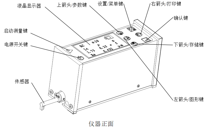
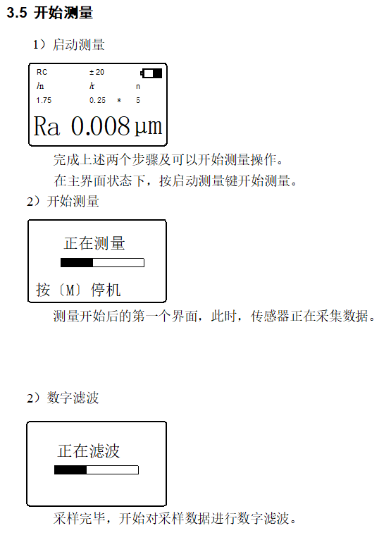
 : Activate the measurement key. Used to start instrument measurement.
 : Power on / off key. On-off key for daily use, it does not turn off the battery and retains stored information. If the instrument will not be used for a long time, turn off the battery switch on the rear of the instrument.
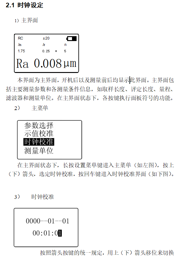
 : Up arrow / parameter key. In the main interface, press this key to enter the parameter display interface, and press Enter to exit.
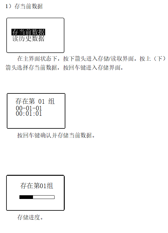
 : Down arrow / store key. In the main interface, press this key to enter the storage record interface.
 : Left arrow / graphic key. In the main interface, press this key to enter the graphic display interface.
 : Right arrow / print key. In the main interface, press this key to start the printer to print all measurement results.
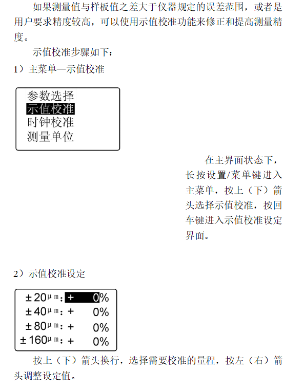
 : Settings / Menu key. In the main interface, press this key to enter the measurement interface setting state. Long press this key for about 3 seconds to enter the main menu interface.
 : Enter confirmation key. In all interfaces, it is used to confirm the result of setting modification or exit this interface.
Special instructions for using the arrow keys:
The general definition of the functions of the four arrows: up and down and left and right: uniformly stipulated in all interfaces that need to be modified. It takes effect only after the measurement conditions are modified and the graphic display interface. It does not work in the main interface. In the main interface, these arrow keys perform only the functions indicated by the characters above.
|
Serial number |
name |
Quantity |
|
1 |
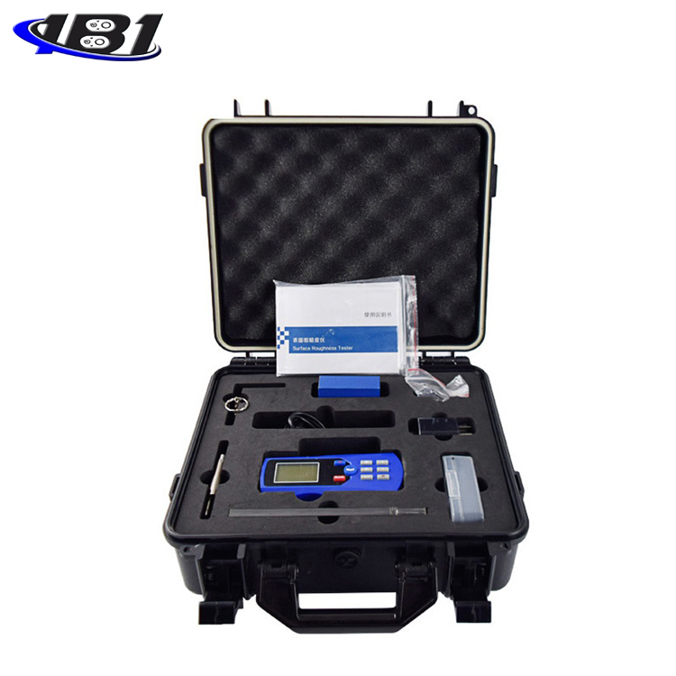
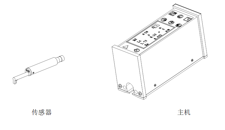
TR200 host |
1 |
|
2 |
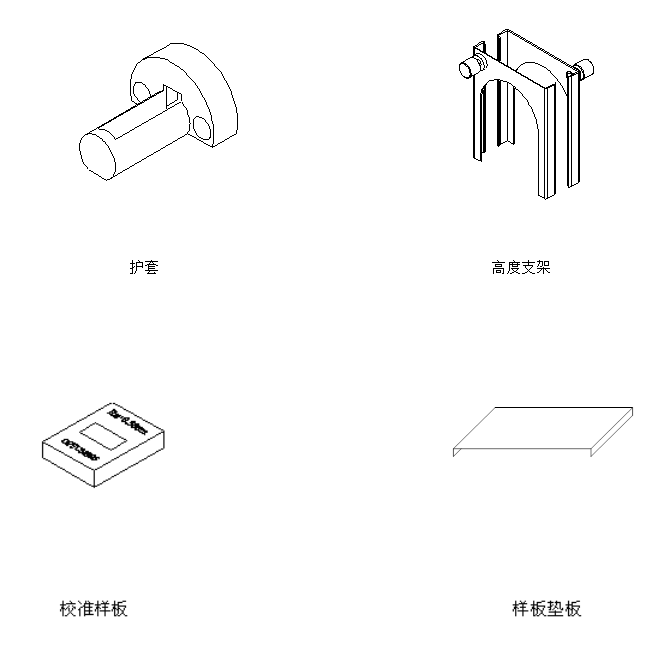
Standard sensor |
1 |
|
3 |
Calibration template |
1 |
|
4 |
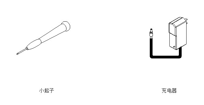
Power Adapter |
1 |
|
5 |
Small screwdriver |
1 |
|
6 |
Template plate |
1 |
|
7 |
user's manual |
1 |
|
8 |
Certificate of conformity |
1 |
Note: The above list is for reference only, and the actual goods and quantity are subject to the packing list.

The soft switch is located in the lower left corner of the panel (as shown in the figure). It is recommended to use it if the instrument is used frequently. When the soft switch is in the off state, the battery still supplies power to the circuit, and the information in the memory and the time setting are saved. Some system information does not need to be reset when the system is turned on next time.
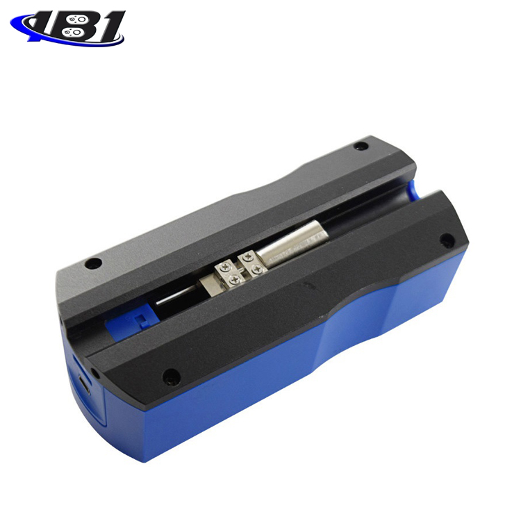
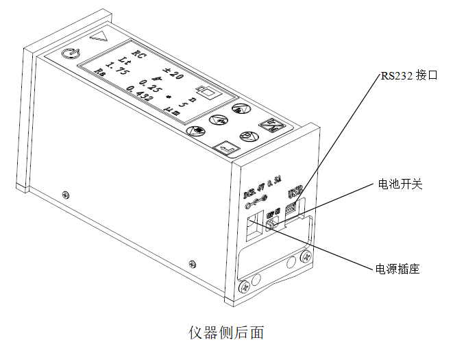
The hard switch is located on the back panel of the instrument (as shown in the figure). If the instrument is not used for a long time, the hard switch should be turned off to better protect the instrument and battery. When the hard switch is turned off, the battery will no longer supply power to the circuit, and the contents of the memory will be reset. It must be reset when the next time it is turned on.
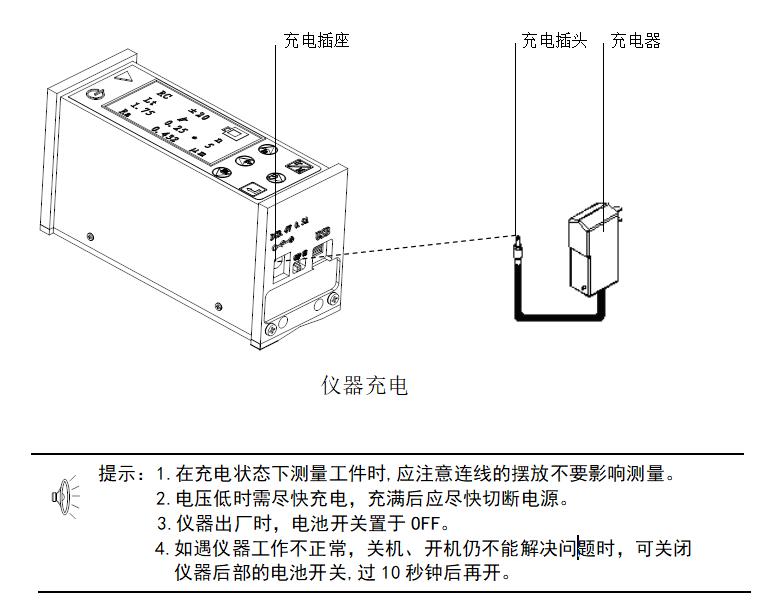
When the instrument indicates that the voltage is too low or cannot be turned on, the instrument should be charged. When charging, as shown in the figure, insert the plug of the charger into the charging socket of the instrument, and then connect the charger to the mains power of 220V / 50Hz to start charging. When the red light is on, it indicates that charging is in progress. When the green light is on, it indicates that the battery is fully charged and can be powered off. The entire charging time is about 3 hours. Be careful not to make the charging time too long. The input voltage of the charger is 220 volts AC, the output is 8.4 volts DC, and the maximum charging current is about 500 mA. This instrument uses a lithium-ion battery, which has no memory effect and can be charged at any time. The instrument can work as usual when charging.
|
name |
content |
|
|
Measuring range |
Z axis (vertical) |
160μm |
|
X axis (horizontal) |
17.5mm |
|
|
Resolution |
Z axis (vertical) |
0.01 μm / ± 20 μm |
|
0.02μm / ± 40μm |
||
|
0.04μm / ± 80μm |
||
|
Measurement item |
parameter |
Ra, Rq, Rz, Rt, Rp, Rv, RS, RSm, Rz (JIS), Ry (JIS), RSk, R3z, Rmax, Rpc, Rmr |
|
standard |
ISO, ANSI, DIN, JIS |
|
|
Graphics |
Roughness profile, support ratio curve, direct profile |
|
|
filter |
RC, PC-RC, Gauss, D-P |
|
|
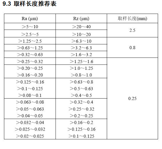
Sampling length (lr) |
0.25, 0.8, 2.5mm |
|
|
Evaluation length (ln) |
Ln = lr × n n = 1 ~ 5 |
|
|
sensor |
Measurement principle |
Displacement differential inductor |
|
Stylus |
Natural diamond, 90 cone angle, 5μm tip radius |
|
|
Force measurement |
<4mN |
|
|
Guide |
Ruby, taxiing radius 40mm |
|
|
Taxi speed |
lr = 0.25, Vt = 0.135mm / s |
|
|
lr = 0.8, Vt = 0. 5mm / s |
||
|
lr = 2, 5, Vt = 1mm / s |
||
|
Return Vt = 1mm / s |
||
|
Indication error |
Not more than ± 10% |
|
|
Indication variability |
Not more than 6% |
|
|
power supply |
Built-in lithium-ion rechargeable battery, charged with 8.4V, 800mA charger |
|
|
Dimensions |
119 × 47 × 65mm |
|
|
weight |
About 380g |
|