support hotline
0577-57572522
I. Use
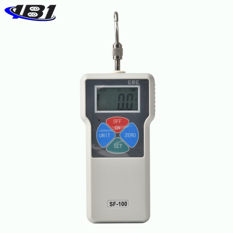
Digital push-pull gauge is a small, simple, multi-functional, high-precision thrust and pull test instrument. It is widely used in electronic appliances, construction hardware, light industrial textiles, auto parts, lighters and other ignition devices, fire equipment, pen-making, Push-pull load, plug-out force test, destructive test, etc. in lock making, fishing gear, chemical industry, power machinery, scientific research institutions and other industries. The digital display has high resolution, high sampling speed, and easy to use. It is a new generation of high-precision push-pull force testing instrument.
Second, the functional characteristics
1. High precision and high resolution.
2. Five test modes and three display modes are available (to maximize test efficiency).
3, N (Newton), kg (kg), lb (pound) three measurement units are available for selection and conversion.
4. Gravity acceleration setting function: Users can input the precise value of gravity acceleration of the place of use. Make testing and unit conversion more accurate.
5. Peak hold function. Keep the peak display until it is manually cleared.
6, automatic peak function, you can freely set the time from 1-9999 seconds.
7. The upper and lower limits can be set for statistical analysis. The buzzer can be alarmed by setting the upper and lower limits beyond the limited range.
8. Data storage function, can store 447 test values.
9, data output function, data can be input to the computer through the data line for various analyses. (It is also suitable for multiple instruments to perform various analyses with a computer at the same time.)
10. Green and environmental protection, 10 minutes of automatic shutdown without operation. By default, 10 minutes can be set to the required automatic shutdown time. When the automatic shutdown is set to 0, it will not automatically shut down.
11. High-quality rechargeable power supply. The charging voltage is available from 100V to 240V, which can be adapted to most areas at home and abroad. There are also short-circuit, leakage, overload protection functions.
12, the unique switch contact on-off force test function, making the switch on-off force test more accurate.
13, 6-digit large screen display.
14, low battery detection shutdown, automatically shut down when the battery power is low, to prevent measurement inaccuracy caused by insufficient power.
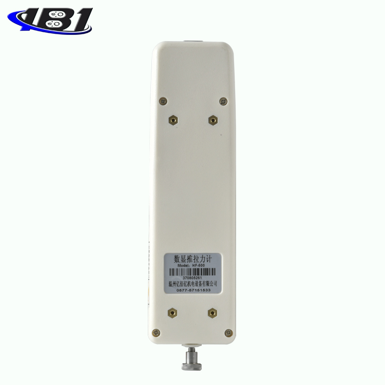
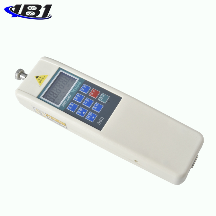
Third, the shape structure
Fourth, model specifications
|
Model specifications |
HF-2 |
HF-3 |
HF-5 |
HF-10 |
HF-20 |
HF-30 |
HF-50 |
HF-100 |
HF-200 |
HF-300 |
HF-500 |
HF-1000 |
|
Maximum load value |
2N |
3N |
5N |
10N |
20N |
30N |
50N |
100N |
200N |
300N |
500N |
1000N |
|
0.2kg |
0.3kg |
0.5kg |
1kg |
2kg |
3kg |
5kg |
10kg |
20kg |
30kg |
50kg |
100kg |
|
|
0.45Lb |
0.65Lb |
1.1Lb |
2.2Lb |
4.5Lb |
6.5Lb |
11Lb |
22Lb |
45Lb |
65Lb |
110Lb |
220Lb |
|
|
Load division |
0.001N |
0.01N |
0.1N |
|||||||||
|
0.0001kg |
0.001kg |
0.01kg |
||||||||||
|
0.001Lb |
0.01Lb |
|||||||||||
|
Sensor structure |
Built-in |
Internal / External |
||||||||||
|
Precision |
± 0.5% |
± 1% |
||||||||||
|
power supply |
7.2V 1.2V × 6 Ni-MH battery pack |
|||||||||||
|
Output Interface |
RS 232 nine-hole socket |
|||||||||||
|
Charging time |
4 ~ 6 hours |
|||||||||||
|
Battery continuous use time |
About 15 hours |
|||||||||||
|
Battery Life |
≥300 times |
|||||||||||
|
charger |
||||||||||||
|
Operating temperature |
5 ℃ ~ 35 ℃ |
|||||||||||
|
Transport temperature |
-10 ℃ ~ 60 ℃ |
|||||||||||
|
Relative humidity |
15% ~ 80% RH |
|||||||||||
|
working environment |
No vibration source and corrosive medium around |
|||||||||||
|
Model specifications |
HF- 2000 |
HF- 3000 |
HF- 5000 |
HF- 10k |
HF- 20k |
HF- 30k |
HF- 50k |
HF- 100k |
HF- 200k |
HF- 300k |
HF- 500k |
HF- 1000k |
HF- 2000k |
|
Maximum load value |
2000N |
3000N |
5000N |
10KN |
20KN |
30KN |
50KN |
100KN |
200KN |
300KN |
500KN |
1000KN |
2000KN |
|
200kg |
300kg |
500kg |
1Kkg |
2Kkg |
3Kkg |
5Kkg |
10Kkg |
20Kkg |
30Kkg |
50Kkg |
100Kkg |
200Kkg |
|
|
450Lb |
650Lb |
1100Lb |
2.2KLb |
4.5KLb |
6.5KLb |
11KLb |
22KLb |
45KLb |
65KLb |
110KLb |
220KLb |
450KLb |
|
|
Load division |
1N |
0.001KN |
0.01KN |
0.1KN |
1KN |
||||||||
|
0.1Kg |
0.0001Kkg |
0.001KKg |
0.01KKg |
0.1KKg |
|||||||||
|
0.1Lb |
0.0001KLb |
0.001KLb |
0.01KLb |
0.1KLb |
|||||||||
|
Sensor structure |
External |
||||||||||||
|
Precision |
± 1% |
||||||||||||
|
power supply |
7.2V 1.2V × 6 Ni-MH battery pack |
||||||||||||
|
Output Interface |
RS 232 nine-hole socket |
||||||||||||
|
Charging time |
4 ~ 6 hours |
||||||||||||
|
Battery continuous use time |
About 15 hours |
||||||||||||
|
Battery Life |
≥300 times |
||||||||||||
|
charger |
Input: AC 100 ~ 240V Output: DC 12V 500mA |
||||||||||||
|
Operating temperature |
5 ℃ ~ 35 ℃ |
||||||||||||
|
Transport temperature |
-10 ℃ ~ 60 ℃ |
||||||||||||
|
Relative humidity |
15% ~ 80% RH |
||||||||||||
|
working environment |
No vibration source and corrosive medium around |
||||||||||||
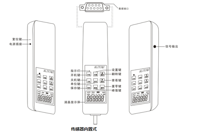
Five, screen display
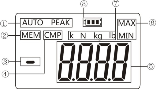
① Three kinds of display: After power-on, when there is no character displayed here, it means \"track mode \" (real-time load measurement method), and the value on the screen changes with the change of load; press \"Peak \" key here When \"PEAK \" is displayed, it means Peak mode, and the display shows the peak value until it is manually cleared; press the\"Peak\" key again. When there is \"AUTO PEAK \" displayed, it means \"autopeak \" (peak hold automatically releases the measurement method). The peak value is automatically saved and cleared after 10 seconds. The peak time of 10 seconds can be freely set. For details, please refer to the following function introduction. (PE.SET) Explanation}.
② Whether there is data storage display: When there is no\"\" MEM\"displayed here, it means that no data is stored in the instrument; when there is\"\"MEM \" displayed here, it means that there is data stored in the instrument; When you press the\"View\" key on the measurement interface to view the saved data, there is\"\" MEM \"flashing here.
③ Push and pull instructions: In this machine, the thrust (pressure) is displayed as a negative value (\"-\"), and the pull force is positive (\"+ \" is not displayed).
④ Comparison function. When setting the comparison value via STOP (for details, refer to the (STOP) Machine stop value description), this function is activated. \"CMP \" is displayed. It can be set separately when needed.
⑤ The measured force value is displayed.
⑥ Reaching the upper and lower limit display: When \"MIN \" is displayed here, it means that the measurement data has reached and fallen below the lower limit; when \"MAX \" is displayed here, it means that the measurement data has reached and Exceeded the upper limit.
三种, three units display: N (ox), kg (kg), lb (pound) three units are displayed separately, converted by pressing the unit key. For HF10K and above specifications, K N (kN), K Kg (ton), and\"K lb (kilogram)\" are displayed here.
电量, power display: When the battery voltage drops below 7.0V, it prompts that the voltage is insufficient and needs to be recharged (it can still be tested when charging). There is a power indicator above the power button. When the charger is plugged in for charging, the indicator first changes from red to green. This process is repeated twice to indicate that the charging is normal. After that, the indicator is red. After the battery is fully charged, the indicator changes. Into green. If the instrument is not used from time to time and the battery power is too low, the indicator light may not turn on when the charger is plugged in. After about half an hour, the indicator light turns red after the battery is awakened. The charging time needs 4 ~ 6 hours.
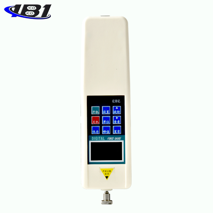
Six, key introduction

1. \"Startup \" key
When you press this key, the power is turned on and the model number is displayed. After powering on, before pressing the\"\" Zero\"key\" to clear, the zero drift value of the analog signal may be displayed on the screen, just press the\"\" Zero\"key\" to clear it.
2. \"Shutdown \" key
In the power-on state, when you press this key, the power is turned off, but the stored saved data will not disappear. When starting up (that is, when the model number is displayed and the measurement interface 0.00 is not displayed), pressing the shutdown key at this time cannot respond.
3. \"Save \" key
In the peak measurement interface state, press this key to save the test data displayed on the screen; in the function setting interface state, press this key to save the set parameters. When some test data is stored in the machine, \"MEM \" is displayed. This machine can store 447 data.
4. \"Settings \" key
For detailed settings, please refer to the description of the various setting methods in \"Features \".
5. \"Unit \" key
Press this key to execute the measurement unit switch, which can display three units of N (Newton), kg (kg) and lb (pound) in a cycle. When the test data is displayed, the unit conversion of the same value can also be completed. In the specifications of HF10K and above, it is composed with the letter\"K\" (KN),\"Kkg (ton)\",\"Klb (kilogram)\".
6. \"Peak \" key
Each time you press this key, there will be a switch between \"PEAK \" display, \"AUTO PEAK \" display or \"PEAK \" disappearing—that is, peak hold, peak hold automatic release, and load real-time value mode switching.
7. \"Flip \" key
This key is only valid in the test interface. When this key is pressed, the measured value displayed on the screen will flip 180 degrees.
8.\"View\" key
When you press this key, the stored test data will be called up and displayed on the screen in sequence. At this time, the word\"\" MEM\"\" will flash-the number of saves will be displayed first, and the saved data will be automatically displayed after 2 seconds. Press the\"Zero Set\" key to return to the measurement interface.
9. \"Zeroing \" key
When you press this key, the test value on the screen will be reset to zero. Note: When the instrument is reset to zero, the instrument can only be reset to zero in the real-time measurement mode and under the peak and automatic peak.
※ Select a lighter fixture or release the applied load and clear it again.
※ On the \"View \" interface, press and hold this key for 4 seconds, all the stored test data can be cleared (it may not be cleared in some states, then restart the machine and then execute this function to clear all saved data) .
Seven, boot display
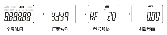
Function introduction
1.Setting function
a. Mode switching: After the display is complete, press the\"\" Settings\"\" key to display\"\" TEST\"\". Press the\"Settings\" key again to display the 0001 mode. Use\"\" \"Key can select different modes. As shown below:
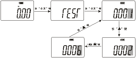
0001 Standard test mode 0002 Push-pull peak mode
0003 Thrust peak mode 0004 Rush peak mode
0005 External node on-off mode 0006 External node on-off mode
0001 Standard test mode (factory default mode): In this mode, three states can be set, namely the real-time load state, peak hold state, and automatic peak state. When \"PEAK \" is not displayed on the display, it is the state of the real-time load, and the test value changes with the change of the load. When the\"Peak\" key is displayed, the word\"PEAK \" is displayed. The displayed test value is the maximum value in the test (regardless of the tension and pressure), which needs to be manually cleared; press the\"\" Peak\"\" key again, and the\"AUTO PEAK\" display will show the automatic peak status. The displayed test The value is the maximum value in the test (regardless of tension and pressure), and it will automatically disappear and return to zero after holding the display for 2 seconds.
0002 Push-pull peak mode: The function of grasping the maximum load value in both pressure and tension directions at the same time. During the connector test, the function of grasping the maximum load of the positive and negative sides of the insertion force and the extraction force is grasped.
0003 Thrust peak mode-during plug-in test, only the maximum load function of the insertion pressure
0004 Pull force peak mode-When plugging and unplugging test, only grasp the function of the maximum load of pulling force.
0005 0006 Switch contact on-off force test mode-accurately measure the load value at the moment of contact on-off.
0005 The maximum force value of the external node from the moment of disconnection to the moment of connection. Connect the two contacts under test to pins 4 and 5 of the data interface, press the\"Peak\" key to select the peak mode, and apply pressure to the switch with a push-pull gauge until the switch is turned on. The measured force value is the force value required to switch on the switch.
0006 The maximum value of an external node from the moment it is turned on to the moment it is turned off. Connect the two contacts under test to pins 4 and 5 of the data interface (using the data plug in the accessory), press the\"Peak\" key to select the peak mode, and apply pressure to the switch by pushing and pulling the force gauge until The switch is turned off, and the measured force value is the force value required to open the switch.
b, each setting item
Press the\"\" Settings\"\" key under the power-on state, the display is\"\" TEST \", press\"\" \"Key, you can view the setting options. \" HIDT \", \" LODT \", \" STOP \", \" LOSET \", \" OFFT \", \" PE.SET \", \"GSET \", \"BACSET \", \"REF \", \"DIR \", \"SHIELD \", \"USR.CAL \", \"RESET \". As shown below:
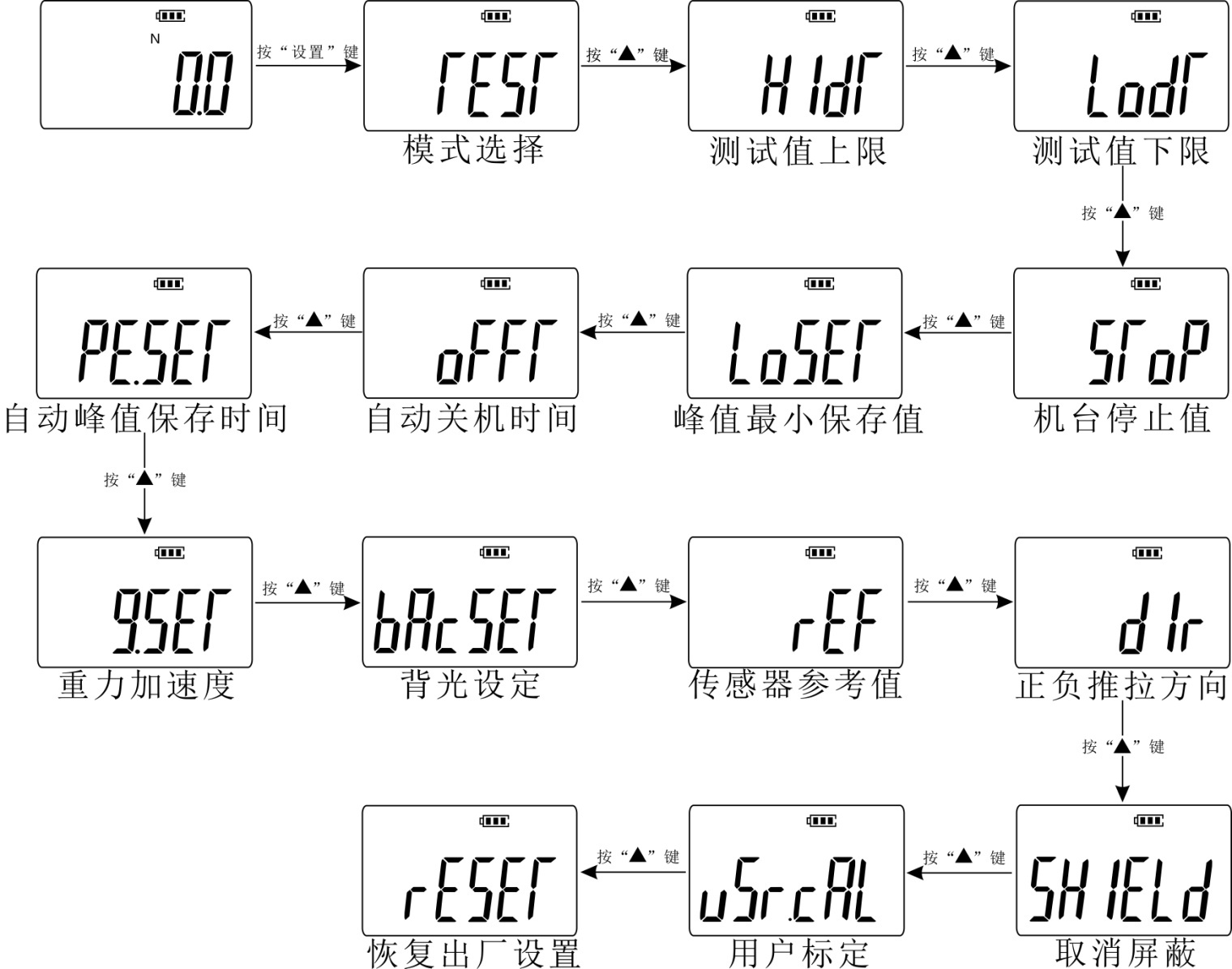
 (HIDT) Test value upper limit setting: Set the upper limit of the test value. The upper limit value defaults to 99% of the full scale. Above the upper limit is out of range, \"MAX \" is displayed. To reset the upper limit, use \"\"Key and \"
 \"Key setting. \" Save \"to return to the setting item interface. As shown below:
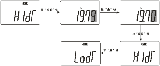
 (LODT) Test value lower limit setting: Set the lower limit of the test value. The lower limit defaults to 0. Below the lower limit is out of range, \"MIN \" is displayed. If you want to reset the lower limit, it is similar to the previous step. Use\"\"\"Key and \"\"Key setting. \" Save\"and return to the setting item interface.
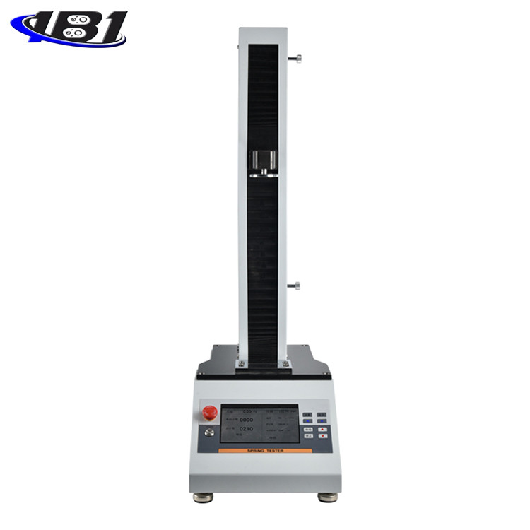
 (STOP) Machine stop value setting. The default state is 99% of full scale. This product is used in combination with our own motor table. When the test value exceeds the set machine stop value, the instrument outputs a 5V signal and the machine receives the signal.
This function operation method:
a. First set the instrument stop value for this instrument: Setting method: power on, when the measurement interface is displayed, press the\"\" Setting\"\" key to enter the machine stop value setting (display (STOP), set its value to the preset value.
b. There is a signal output jack on the right side of the instrument (refer to the above\"\" Outline Structure Drawing\"for details). Insert one end of the signal output cable into this jack (socket) and the other end into the electric test bench produced by our company. The jack (socket) marked as the signal input on the top (this signal output cable is a standard accessory of the electric test bench).
c. Start the electric test bench produced by our company, and when the test force exceeds the stop value of the machine, the motor will automatically stop running.
 (LOSET) Peak minimum saved value:Minimum peak save value. In peak mode, when the current value is less than this value, the peak value will not be saved.
 (OFFT) Automatic shutdown time setting: Under this setting item, use \"
 \"Key selection, you can set 10 minutes to 90 minutes to automatically shut down, you can also set \" 00 \"not to automatically shut down. If you choose not to automatically shut down, press the \" Save \"key after selection to complete the setting. Return to the options screen. The instrument is set to 10 minutes by default.
 (PE.SET) Automatic peak save time: Automatic peak save time, the unit is second, the default value is 10, the setting cannot set this value to 0.
 (BACSET) Backlight function setting: Under this setting item, use \"
 \"Key selection, if selected \"
 (YES) \"means turn on the backlight function, select \"
 (NO) \"means to turn off the backlight. After selecting, press \" Save \"key to save and return to the setting item interface.
 (REF) sensor reference value: manufacturer's reference value, users do not need to pay attention.
 (DIr) Positive and negative push-pull direction: Used to switch the positive and negative directions of the push-pull force meter.
 (SHIELD) Cancel Mask: Cancel the mask to display data below 1% of full scale. Press \"YES \" to cancel, press \"NO \" to cancel.
 (USR.CAl) user calibration: Under this setting item, the user can choose \"1 \" (full-scale calibration), \"2 \" (full-scale 1/2 calibration), \"4 \" (full 1/4 scale), \"8 \" (1/8 scale full scale), \"16 \" (1/16 scale full scale).
 (RESET) Restore factory settings function:Under this setting item, press \"Settings \" key to restore the factory settings and the machine shuts down. If you use the machine to restart.
Nine, test
Press the \"On \" key to turn on the power and use the factory default settings to directly perform the test as required or press the Set key to select the test mode and perform the test.
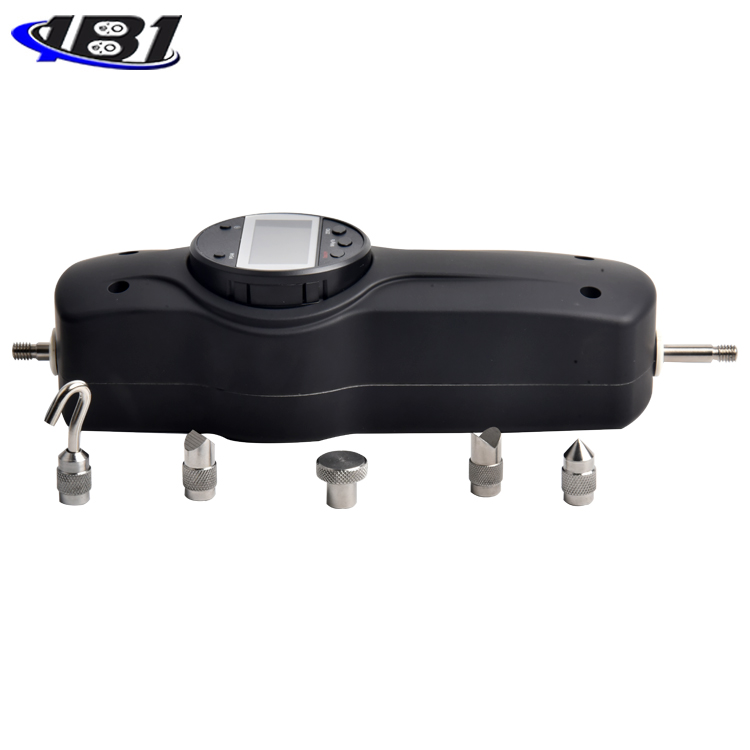
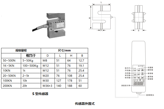
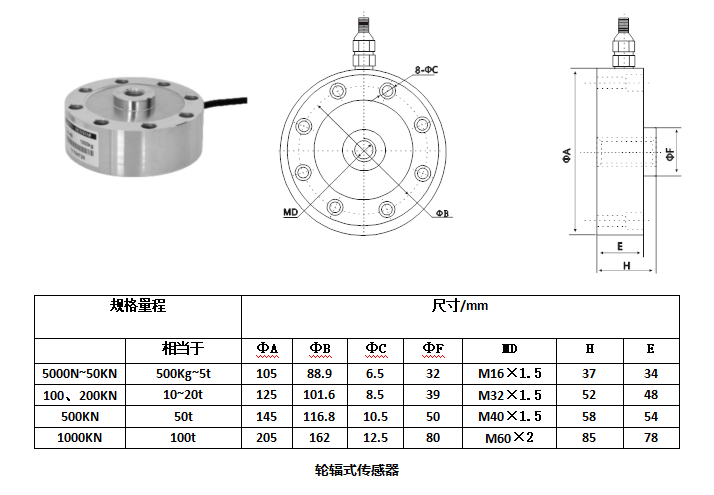
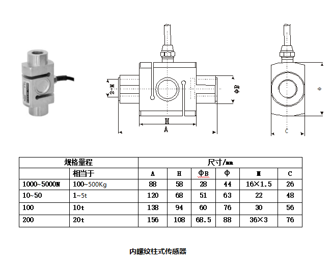
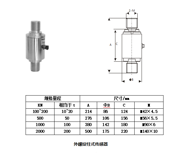
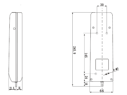
1. Select the appropriate test fixture to be installed on the push-pull gauge (for the self-made fixture, please refer to the relevant data in \"Outline and Installation Dimension Drawing \".
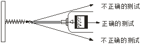
2. Please hold the push-pull meter firmly or install the push-pull meter on a suitable test machine for testing. When testing, please make the test force and the push-pull rod of the push-pull meter in a straight line so as to measure the accurate load .
3. After the test is completed, remove the load, turn off the power, remove the jig, clean the objects and put them back in the tool box for the next use.
X. Introduction to storing data and connecting to a computer
1.Stored data
Press the\"\" Save\"key to save the data. The saved value is the value displayed on the current screen. The word\"\"MEM \" will be displayed on the display. The stored data can also be saved after shutdown. When you use \"View \" to view the saved data, \"MEM \" flashes, the number of times of saving appears first, and the value of saving automatically appears after 2 seconds. Press \"Zero \" key to exit saving and directly enter the test. The data can also be input into a computer for analysis and processing. This machine can store 447 data. When there are more than 447 data, the subsequent data will not be saved.
Data clear
When viewing the interface, press the\"Zero Zero\" key for more than four seconds, all the saved data will be cleared, and the word\"\" MEM \"will disappear.
3. Introduction to using computer
a. Use the\"Data Export Program\" in the CD-ROM to export the data saved in the instrument to the computer. View, print, test times, average, maximum, minimum, and determine whether the test results meet the set requirements. (For details, please refer to the instructions in\"Data Export Procedure\")
b. Use the\"Synchronous Test\" in the CD to realize the curve of force value and time. (For details, please refer to the description in\"Synchronous Test\")
4. If connecting with PLC, custom modbus protocol is required.
Eleven safety precautions
1. Matters needing attention:
a. After purchasing this instrument, if the instrument has insufficient power, it needs to be charged for 4 ~ 6 hours before it can be used normally.
b. To purchase this instrument, you must use the RS232 computer cable included in the accessories distributed by our company.
c. If the operation is incorrect, it may damage the instrument or cause serious accidents. This manual points out important matters for preventing accidents and how to use the instrument. Please read this manual carefully before use, and keep it in a safe place for future reading.
d. If it is testing the impact load, please choose the model with the maximum load double the impact load to be tested.
2. Warnings:
a. During the destructive test, wear a protective mask and gloves to prevent the splashing material from hurting the human body during the test.
b. Do not use fixtures that are damaged or severely deformed. Please refer to the relevant parameters in this manual for the self-made jig (the company has other kinds of jigs, customers can choose according to their needs; purchase separately).
C. Do not use the instrument beyond its maximum range. Doing so may cause damage to the sensor or even an accident.
d. When the test value exceeds 100% of the full scale, the buzzer will beep continuously. At this time, please quickly remove the added load or reduce the load. When the test value exceeds 120% of the full scale, the instrument may be damaged.
3. Solve the crash state: When the instrument crashes unexpectedly, press a small round rod on the left side of the instrument and press a button labeled\"\" Reset\"\" to quickly reset and shut down.
4. Safety matters:
a. Please use the matching charger to charge, otherwise it will cause circuit failure or even fire.
b. Do not use a power source other than the rated voltage of the charger, otherwise it may cause electric shock or fire.
c. Do not pull out or plug in the power supply with wet hands, otherwise it may cause electric shock.
d. Do not pull the power cord of the charger to pull out the plug, so as to avoid the electric wire being torn and being shocked.
e. Please use a soft cloth to clean the machine. Immerse the cloth in water soaked in detergent and wring it dry before removing dust and dirt. Note: Do not use volatile chemicals to clean the unit (such as volatile agents, thinners, alcohol, etc.).
f. Do not operate the machine in the following environments
① A humid environment ② A dusty environment ③ A place where oil or chemicals are used ④ A place with a vibration source around
g. Please use and store within the specified temperature and humidity range, otherwise it may cause the instrument to malfunction.
h. Do not disassemble, repair or modify the machine yourself. These actions may cause permanent failure of the instrument.
i. Other outstanding matters needing attention in safety production.
Confirmation items of J, HF series push-pull gauge before sending for repair
|
power supply |
symptom |
Cause or phenomenon |
Dispose |
|
Press \"Startup \" key no display |
Battery is dead |
Recharge |
|
|
Unable to charge |
Charging using a converter that does not meet the specifications |
Please confirm: AC110V AC220V |
|
|
The charging indicator is off |
Battery is too low and requires a wake-up charging time |
Charge the battery for half an hour without the indicator light. If the instrument is normal, the indicator light will re-light. |
|
|
test value |
Test value is not accurate |
Excessive error |
Need to return to factory for correction |
|
other |
Unexpected crash |
No response when pressing any key |
Press the \"Reset \" key with the needle |
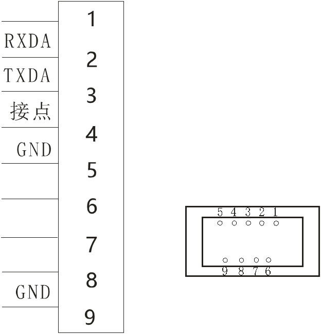
Twelve, data interface (9PIN)
|
Lead feet |
Features |
|
PIN4 PIN5 |
Contact signal |
|
PIN2 PIN3 PIN5 |
Rs232 interface to computer |
Thirteen, outline and installation dimensions
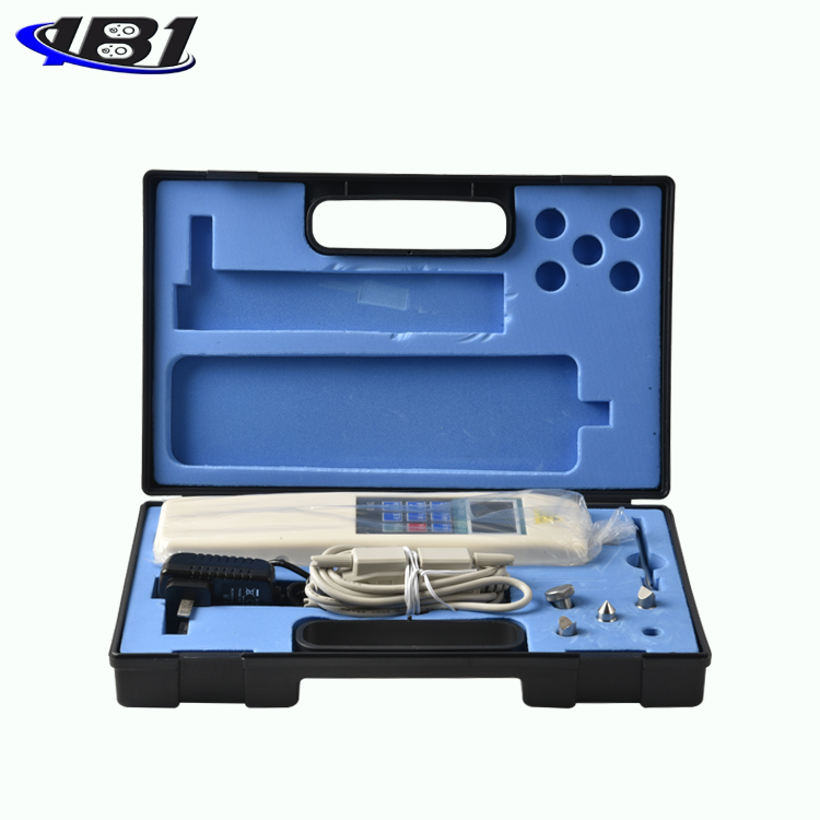
14. Details of Random Attachments
|
|
charger |
Compression fixture |
Stretching fixture |
Extension |
Mounting screws |
Manual |
Inspection certificate |
Certificate of conformity |
|
-2 |
1 |
4 |
1 |
1 |
4 |
1 |
1 |
1 |
|
-3 |
1 |
4 |
1 |
1 |
4 |
1 |
1 |
1 |
|
-5 |
1 |
4 |
1 |
1 |
4 |
1 |
1 |
1 |
|
-10 |
1 |
4 |
1 |
1 |
4 |
1 |
1 |
1 |
|
-20 |
1 |
4 |
1 |
1 |
4 |
1 |
1 |
1 |
|
-30 |
1 |
4 |
1 |
1 |
4 |
1 |
1 |
1 |
|
-50 |
1 |
4 |
1 |
1 |
4 |
1 |
1 |
1 |
|
-100 |
1 |
4 |
1 |
1 |
4 |
1 |
1 |
1 |
|
-200 |
1 |
4 |
1 |
1 |
4 |
1 |
1 |
1 |
|
-300 |
1 |
4 |
1 |
1 |
4 |
1 |
1 |
1 |
|
-500 |
1 |
4 |
1 |
1 |
4 |
1 |
1 |
1 |
|
-1000 (built-in) |
1 |
4 |
1 |
1 |
4 |
1 |
1 |
1 |
|
-1000 (external) |
1 |
3 |
2 |
- |
4 |
1 |
1 |
1 |
|
-2000 |
1 |
3 |
2 |
- |
4 |
1 |
1 |
1 |
|
-3000 |
1 |
3 |
2 |
- |
4 |
1 |
1 |
1 |
|
-5000 |
1 |
3 |
2 |
- |
4 |
1 |
1 |
1 |
|
-10K |
1 |
3 |
2 |
- |
4 |
1 |
1 |
1 |
|
-20K |
1 |
3 |
2 |
- |
4 |
1 |
1 |
1 |
|
-30K |
1 |
3 |
2 |
- |
4 |
1 |
1 |
1 |
|
-50K |
1 |
3 |
2 |
- |
4 |
1 |
1 |
1 |
|
-100K |
1 |
3 |
2 |
- |
4 |
1 |
1 |
1 |
|
-200K |
1 |
3 |
2 |
- |
4 |
1 |
1 |
1 |
|
-300K |
1 |
- |
- |
- |
4 |
1 |
1 |
1 |
|
-500K |
1 |
- |
- |
- |
4 |
1 |
1 |
1 |
|
-1000K |
1 |
- |
- |
- |
4 |
1 |
1 |
1 |
|
-2000K |
1 |
- |
- |
- |
4 |
1 |
1 |
1 |
Note: computer connection and software are optional


 (G.SET)
 DC9.4V
 DC9.4V