support hotline
0577-57572522
I. Uses
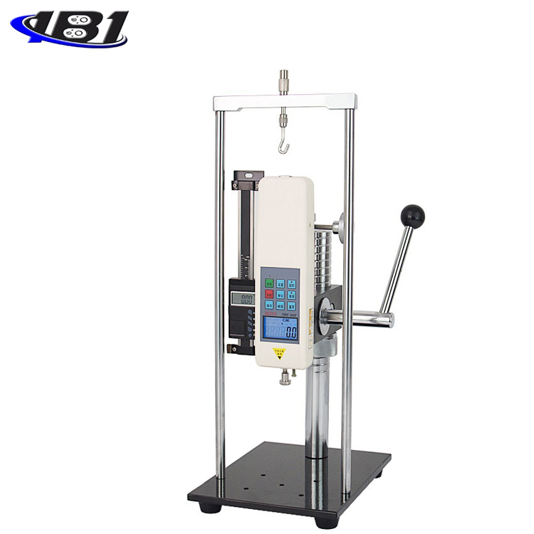
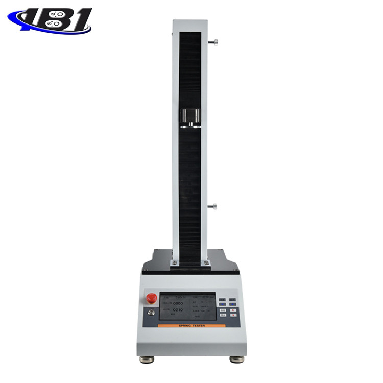
SF series digital push-pull force meter is a new generation of digital push-pull force meter developed by our company. The volume is 1/2 of the original, which is convenient for users to carry around. It is a simple operation thrust and tensile testing instrument. It is widely used for push-pull load test, plug-out force test, damage test, etc. of various products. It can be combined with various machines and fixtures to form small-scale experimental machines for different purposes.
Second, the functional characteristics
1. Digital display, easy to read and high precision.
2, light weight, small size, easy to carry.
3. Unit display: N, Kg and Lb switch each other.
4, the battery has short circuit, leakage, overload protection, the battery has a low battery reminder, using 3.7V lithium battery power, at the same time no operation for ten minutes will automatically shut down.
5, with three measurement modes: real-time, peak, first peak free switching.
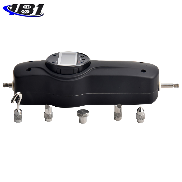
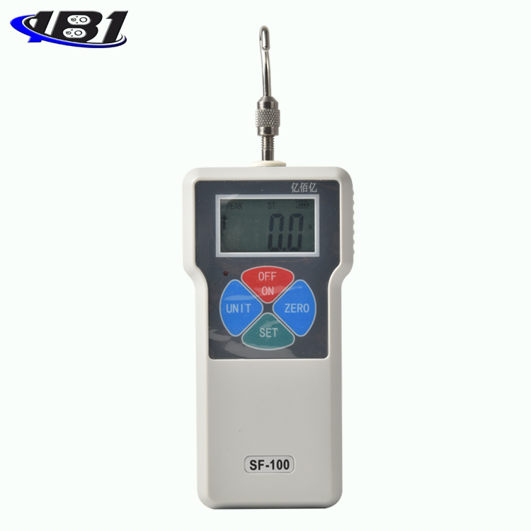
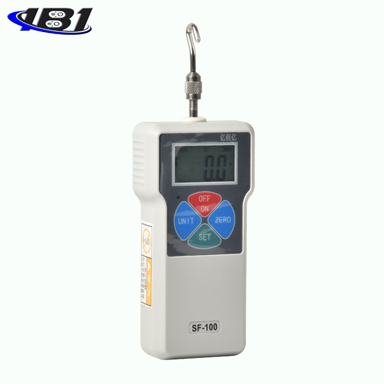
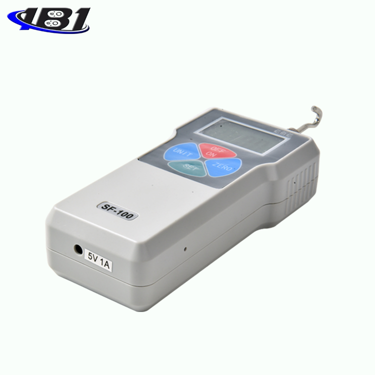
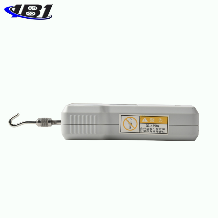
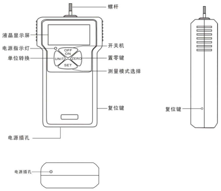
Third, the shape structure
Fourth, the specifications
|
Model specifications |
SF-2 |
SF-3 |
SF-5 |
SF-10 |
SF-20 |
SF-30 |
SF-50 |
SF-100 |
SF-200 |
SF-300 |
SF-500 |
|
Maximum load value |
2N |
3N |
5N |
10N |
20N |
30N |
50N |
100N |
200N |
300N |
500N |
|
0.2kg |
0.3kg |
0.5kg |
1kg |
2kg |
3kg |
5kg |
10kg |
20kg |
30kg |
50kg |
|
|
0.45Lb |
0.65Lb |
1.1Lb |
2.2Lb |
4.5Lb |
6.5Lb |
11Lb |
22Lb |
45Lb |
65Lb |
110Lb |
|
|
Load division |
0.001N |
0.01N |
0.1N |
||||||||
|
0.001kg |
0.001kg |
0.01kg |
|||||||||
|
0.001Lb |
0.001Lb |
0.01Lb |
|||||||||
|
Sensor structure |
Built-in |
||||||||||
|
Precision |
± 0.5% |
||||||||||
|
power supply |
3.7V lithium battery |
||||||||||
|
Charging time |
4 ~ 6 hours |
||||||||||
|
Battery continuous use time |
About 15 hours |
||||||||||
|
Battery Life |
≥300 times |
||||||||||
|
charger |
Input: AC 100 ~ 240V 50 / 60HZ Output: DC 5V 1000mA |
||||||||||
|
Operating temperature |
5 ℃ ~ 35 ℃ |
||||||||||
|
Transport temperature |
-10 ℃ ~ 60 ℃ |
||||||||||
|
Relative humidity |
15% ~ 80% RH |
||||||||||
|
working environment |
No vibration source and corrosive medium around |
||||||||||
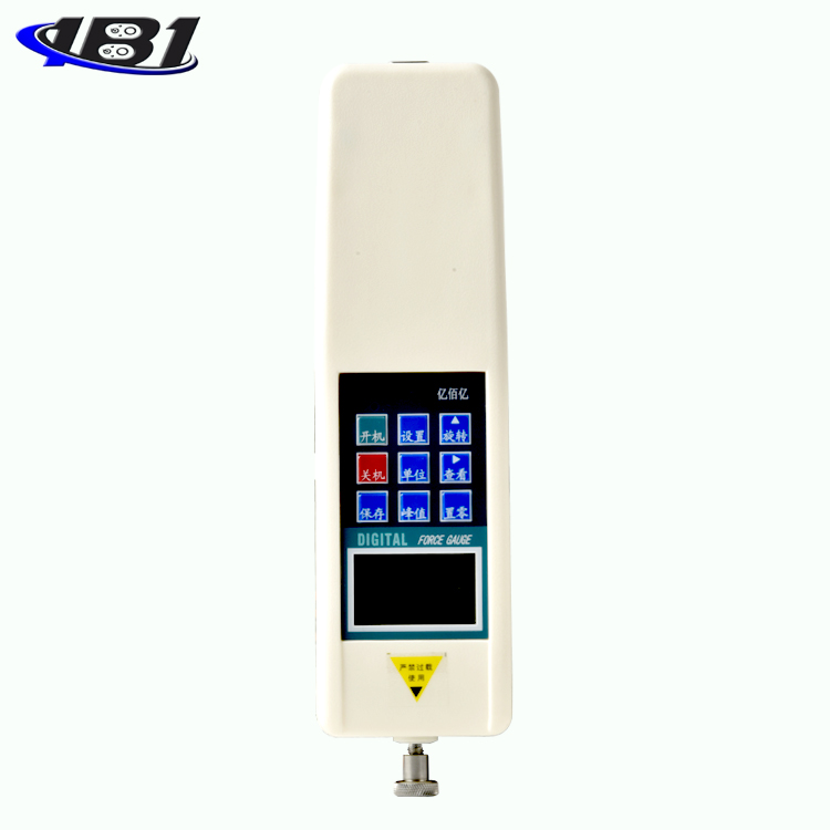
Five, screen display
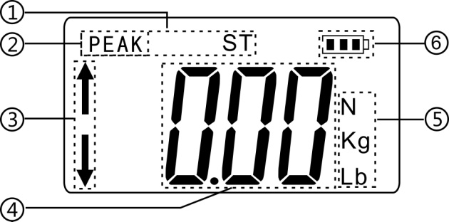
① First peak: When in\"peak mode\", press the\"SET\" key, and\"PEAK ST\" appears on the interface, indicating that it is in\"first peak mode\", and record the measured values during a period The first wave peak.
② Peak mode: After powering on, enter the measurement interface and press \"SET \" key to enter \"Peak mode \" to record the maximum force value measured in a period.
③ Push-pull force indication: The push-pull meter does not move, the upper arrow shows the pull force, and the lower arrow shows the push force.
④ 、 Measurement force value display.
⑤ 、 Three units display: N (ox), kg (kg), lb (pound) are displayed separately, and converted by pressing \"UNIT \" key.
⑥, battery display.
Six, key introduction
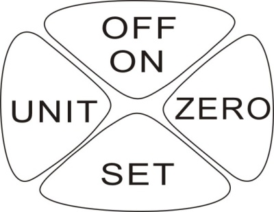
OFF / ON (\"On / Off \" key): When this key is pressed, the power is turned on and the measurement interface appears. When shutting down, press this key again to shut down.
ZERO (\"Zero \" key): When this key is pressed, the test value on the screen will be reset to zero.
SET (\"mode switch \" key): Press this key in the measurement interface to enter the peak or first peak measurement mode; press and hold the\"\" SET \"key for 5-6 seconds in the measurement interface to enter the setting item interface.
UNIT (\"Unit switch \" key): When this key is pressed, three different units can be switched.
Seven, boot display
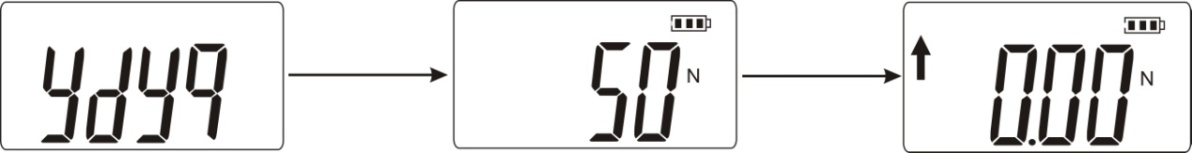
Function introduction
a. Setting items:
After booting, press the\"\" SET\"\" key for 5 to 6 seconds, then release it to enter the setting interface, display\"\" HIDT \", and then press \" UNIT \"continuously, and other setting items will appear in sequence: \" LODT \", \" L.SET \", \" OFFT \", \" G.SET \", \" BAC.S \", \" REF \", \" DIR \", \" SHIE \" , \"CAL.B \", \"R.SET \", as shown below:
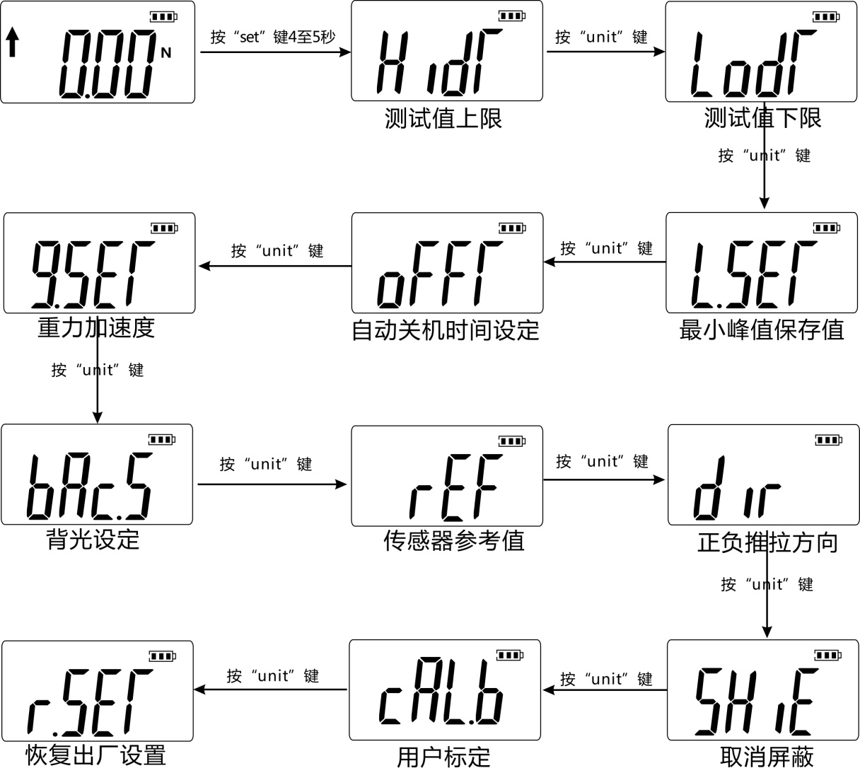
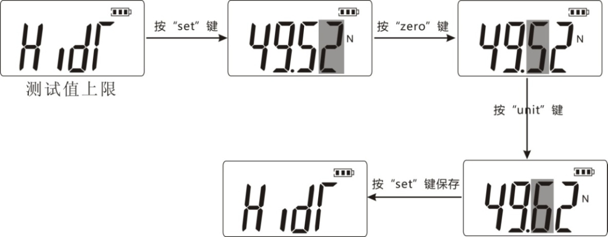
 (HIDT) Test value upper limit setting: Set the upper limit of the test value. The upper limit value defaults to 99% of the full scale. Above the upper limit is out of range and the instrument will beep. If you want to reset the upper limit, you can use the\"\" UNIT\"\" key and the\"\" ZERO \"key to set it. Press \"SET \" key to save and return to the setting item interface automatically. As shown below:
 (LODT) Test value lower limit setting: Set the lower limit of the test value. The lower limit defaults to 0. Below the lower limit is out of range and the instrument will beep. If you want to reset the lower limit, it is similar to the previous step. Use the\"\" UNIT\"\" and\"\" ZERO \"keys to set. Press \"SET \" key to save and return to the setting item interface automatically.
 (L.SET) Peak minimum saved value: The minimum peak saved value. In the peak mode, when the current value is less than this value, the peak value will not be saved.
 (OFFT) Automatic shutdown time setting: Under this setting item, use the\"\" UNIT\"\" key and the\"\" ZERO \"key to set, you can set the automatic shutdown from 1 minute to 9999 minutes, or \" 00 \"Does not shut down automatically. If you choose not to shut down automatically, press \"SET \" key to finish the setting. You are returned to the options screen. The instrument is set to 10 minutes by default.
 (G.SET) Gravity acceleration setting: The user can set the gravity acceleration value according to the location of the area. The default value is 9.800.
 (BAC.S) Backlight function setting: Under this setting item, use \"UNIT \" key to select, if you choose \"
 (YES) \"means turn on the backlight function, select \"
 (NO) \"means to turn off the backlight. After selecting, press the\"\"SET\" key to save and return to the setting item interface.
 (REF) sensor reference value: manufacturer's reference value, users do not need to pay attention.
 (DIR) Positive and negative push-pull direction: Used to switch the positive and negative directions of the push-pull force meter.
 (SHIE) Cancel mask: Cancel mask can display the data below 1% of full scale. Press \"YES \" to cancel, press \"NO \" to cancel.
 (CAL.b) User calibration: User calibration: Under this setting item, the user can choose \"1 \" (full-scale calibration), \"2 \" (full-scale 1/2 calibration), \"4 \"(1/4 full scale calibration), \" 8 \"(1/8 full scale calibration), \" 16 \"(1/16 full scale calibration).
 (R.SET) Factory reset function: Under this setting item, press \"SET \" key to restore factory settings and the machine shuts down. If you use the machine to restart.
Nine, test
Press the \"On \" key to turn on the power, and use the factory default settings to perform the test directly or select the test mode to perform the test.
1. Select the appropriate test fixture to be installed on the push-pull gauge (for the self-made fixture, please refer to the relevant data in \"Outline and Installation Dimension Drawing \".
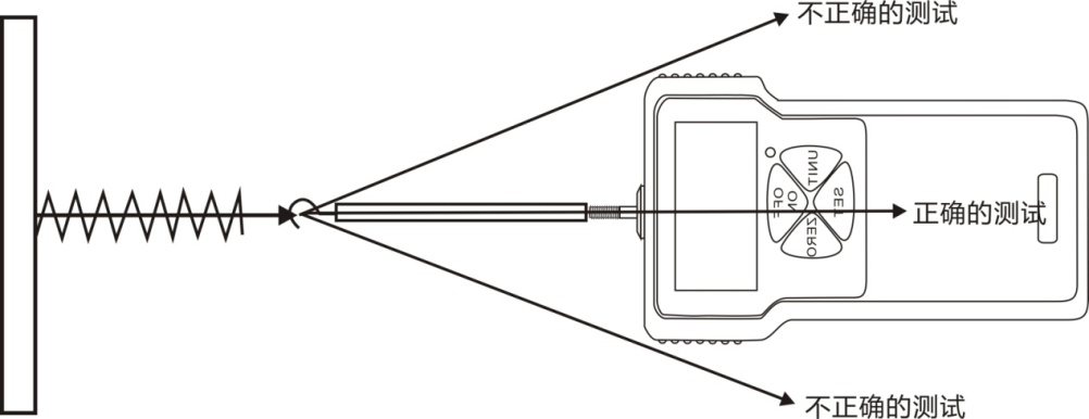
2. Please hold the push-pull meter firmly or install the push-pull meter on a suitable test machine for testing. When testing, please make the test force and the push-pull rod of the push-pull meter in a straight line so as to measure the accurate load .
3. After the test is completed, remove the load, turn off the power, remove the jig, clean the objects and put them back in the tool box for the next use.
Ten, safety precautions
1. Matters needing attention:
a. After purchasing this instrument, if the instrument has insufficient power, it needs to be charged for 4 ~ 6 hours before it can be used normally.
b. If the operation is incorrect, it may damage the instrument or cause serious accidents. This manual points out important matters for preventing accidents and how to use the instrument. Please read this manual carefully before use, and keep it in a safe place for future reading.
c. If the impact load is to be tested, select a model with a maximum load that is twice as large as the impact load to be tested.
2. Warnings:
a. During the destructive test, wear a protective mask and gloves to prevent the splashing material from hurting the human body during the test.
b. Do not use fixtures that are damaged or severely deformed. Please refer to the relevant parameters in this manual for the self-made jig (the company has other kinds of jigs, customers can choose according to their needs; purchase separately).
C. Do not use the instrument beyond its maximum range. Doing so may cause damage to the sensor or even an accident.
d. When the test value exceeds 100% of the full scale, the buzzer will beep continuously. At this time, please quickly remove the added load or reduce the load. When the test value exceeds 120% of the full scale, the instrument may be damaged.
3. Solve the crash state: When the instrument crashes unexpectedly, press a small round rod on the right side of the instrument with a button labeled\"\" Reset\"\" to quickly reset and shut down.
4. Safety matters:
a. Please use the matching charger to charge, otherwise it will cause circuit failure or even fire.
b. Do not use a power source other than the rated voltage of the charger, otherwise it may cause electric shock or fire.
c. Do not pull out or plug in the power supply with wet hands, otherwise it may cause electric shock.
d. Do not pull the power cord of the charger to pull out the plug, so as to avoid the electric wire being torn and being shocked.
e. Please use a soft cloth to clean the machine. Immerse the cloth in water soaked in detergent and wring it dry before removing dust and dirt. Note: Do not use volatile chemicals to clean the unit (such as volatile agents, thinners, alcohol, etc.).
f. Do not operate the machine in the following environments
① A humid environment ② A dusty environment ③ A place where oil or chemicals are used ④ A place with a vibration source around
g. Please use and store within the specified temperature and humidity range, otherwise it may cause the instrument to malfunction.
h. Do not disassemble, repair or modify the machine yourself. These actions may cause permanent failure of the instrument.
i. Other outstanding matters needing attention in safety production.
J. Confirmation items before sending the push-pull meter for repair
|
power supply |
symptom |
Cause or phenomenon |
Dispose |
|
Press \"Startup \" key no display |
Battery is dead |
Recharge |
|
|
test value |
Test value is not accurate |
Excessive error |
Need to return to factory for correction |
|
other |
Unexpected crash |
No response when pressing any key |
Press the \"Reset \" key with the needle |
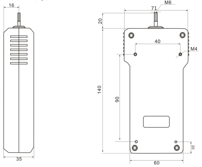
Eleven, appearance and installation dimensions
12. Details of random attachments
|
|
charger |
Fixture head |
Manual |
Inspection certificate |
|
-2 |
1 |
4 |
1 |
1 |
|
-3 |
1 |
4 |
1 |
1 |
|
-5 |
1 |
4 |
1 |
1 |
|
-10 |
1 |
4 |
1 |
1 |
|
-20 |
1 |
4 |
1 |
1 |
|
-30 |
1 |
4 |
1 |
1 |
|
-50 |
1 |
4 |
1 |
1 |
|
-100 |
1 |
4 |
1 |
1 |
|
-200 |
1 |
4 |
1 |
1 |
|
-300 |
1 |
4 |
1 |
1 |
|
-500 |
1 |
4 |
1 |
1 |