support hotline
0577-57572522
I. Applicable occasions
DTL-ESZ rope tension meter is suitable for power industry, communication industry, transportation industry, glass wall curtain industry, ropeway operation industry, construction industry, playground, tunnel construction, fishery fishing and major scientific research institutes and teaching institutions, Detection mechanism and occasions involving rope and wire rope tension.
Second, the functional characteristics
1. The rope structure with tension force can be measured directly without disassembly.
2. Light weight, simple structure, convenient operation, suitable for any occasion.
3, stable performance, high measurement accuracy, with the system automatic compensation function, when the measured cable specifications and dynamometer cable number specifications are the same, the accuracy within the rated range can reach 2%.
4, with fifteen kinds of wire diameter measurement function, wider measurement range.
5. Scope of application: Suitable for flexible and stretched cables. Such as various steel ropes, high-strength ropes, etc.
6, accuracy level: 2 to 6% of the MAX function (depending on the form and characteristics of the rope).
7. Rope diameter: ¢ 6 ~ ¢ 40mm.
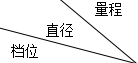
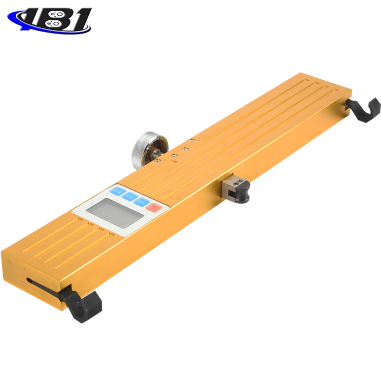
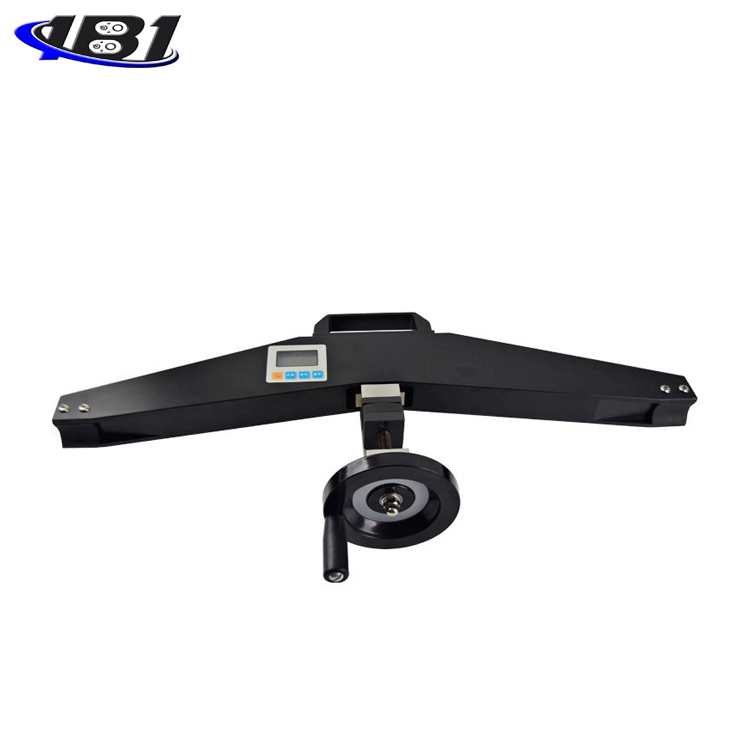
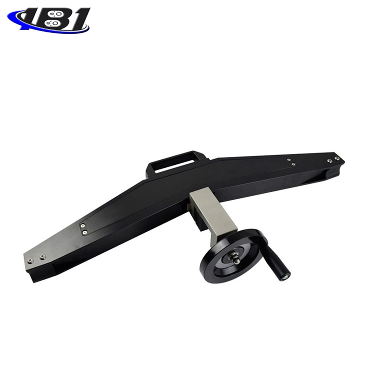
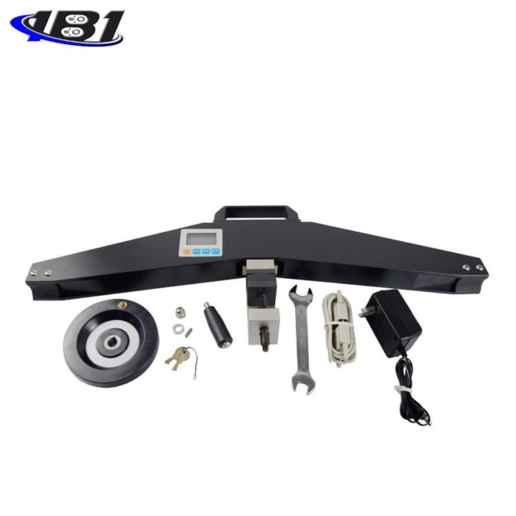
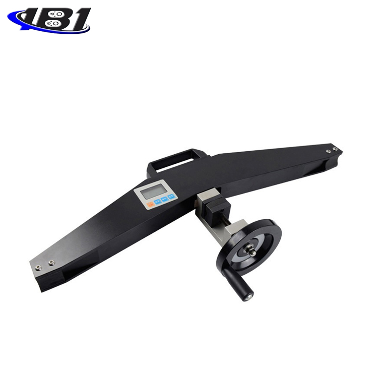
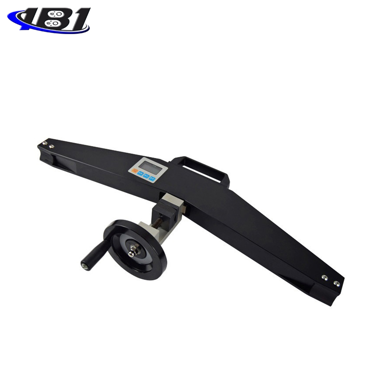
Third, the shape structure

Fourth, model specifications
|
Model specifications |
DTL-ESZ-20 |
DTL-ESZ-50 |
DTL-ESZ-100 |
DTL-ESZ-200 |
|
MAX load value (KN) |
20 |
50 |
100 |
200 |
|
Load division value (KN) |
0.01 |
0.01 |
0.1 |
0.1 |
|
Output Interface |
Rs232 nine-hole socket |
|||
|
power supply |
Rechargeable battery charger (charging voltage 100V ~ 240V) |
|||
|
Operating temperature |
5 ℃ ~ 35 ℃ |
|||
|
Transport temperature |
-10 ℃ ~ 60 ℃ |
|||
|
Relative humidity |
15% ~ 80% RH |
|||
|
working environment |
No vibration source and corrosive medium around |
|||
|
net weight |
5kg |
|||
|
Dimensions |
650 × 375 × 100 |
|||
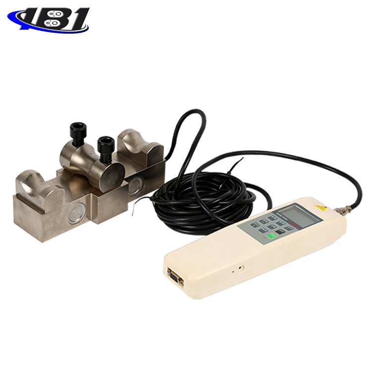
V. working principle
There are two types of cable force measurement: interventional and non-intrusive. The so-called interventional force measurement refers to connecting a tension sensor after the cable is disconnected at the end or span of the cable, and directly reading the cable force. This is the most accurate and intuitive method of force measurement, as shown in the figure below. As shown in 1, 2.

This kind of force measurement method has a large investment and is only suitable for experimental research and individual projects with large tonnage and high requirements. It is not suitable for prestressed structural projects with a large amount of cables.
There are also two methods of non-intrusive force measurement. One is the vibration frequency measurement method, that is, the natural vibration period T of the cable is a function of the internal tension H of the cable, the length of the cable L, and the mass W of the cable. The vibration period T of the cable can be used to calculate the tensile force H in the cable. The principle is relatively simple, but the seismic signal is converted into a signal and processed by the computer before the cable force value is output. This process requires a lot of instruments and equipment, and it is difficult for workers to master, and it is not convenient for high-altitude operations. In addition, the support conditions of the cable end have an impact on the vibration period and the accuracy of the cable force measurement. Another principle for measuring cable force is based on the principle of mechanics. As shown in the figure below, there is a functional relationship between the lateral displacement δ of the cable force and the cable's tensile force H, lateral force P, and the length of the cable. When the displacement is maintained at a certain value, the larger the pulling force H is, the larger the lateral force P is.

The force sensor outputs the lateral force P, which is converted into a cable pulling force after being processed by a microprocessor, and then displayed by a liquid crystal. The above principle is also relatively simple, but the relationship between the lateral force and the cable force is still related to the diameter of the cable and the cross-sectional structure. The elongation of the rope and the size of the tensile force, etc., we deal with the correction by the microprocessor and accurate calibration. Then get the correct and stable cable force. Can pass the test and inspection, and has reached the level of similar foreign products.
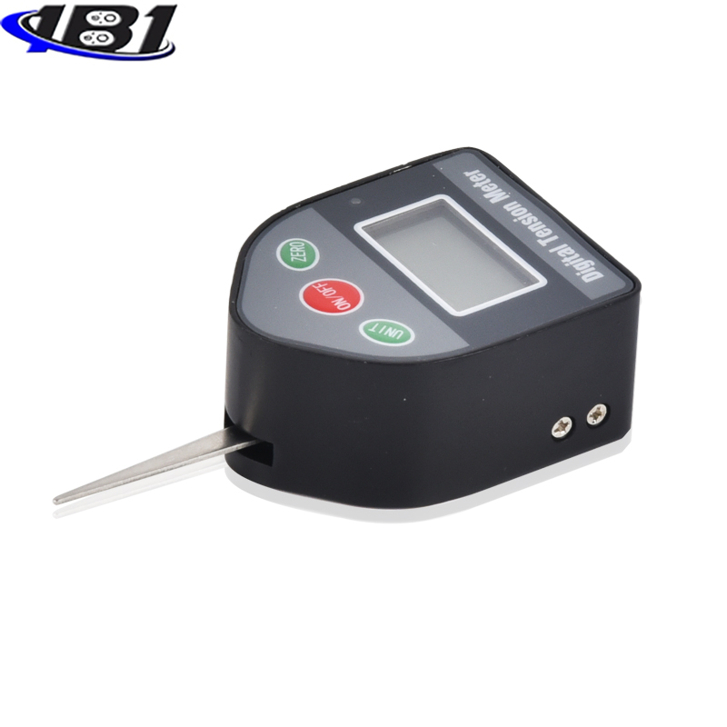
Screen display

1.PEAK display
When \"PEAK \" is displayed, it means Peak mode (peak hold mode), the display shows the peak value until it is manually cleared; when \"PEAK \" is not displayed, it means \"track mode \" (real time load value mode) The value on the screen changes with the load.
2.MEM display
\"MEM \" will be displayed when data is stored. When you press the\"\" Save\"key to view the memorized data,\"\"MEM \" flashes.
Unit display
The letter \"K \" is combined with \"N \", \"kgf \", and \"lbf \" to form \"KN (kiloton) \", \"t (ton) \", \"Klb (Thousand pounds) \"as shown:
4.MAX, MIN display
When the measured value is greater than the MAX value, MAX is displayed;
When the measured value is less than the MIN value, MIN is displayed.
1.Power display
Power level display And low battery alert.
Seven, key introduction

1. ON / OFF key: can be used to turn on and off.
2. Setting key: The user can use this key to enter the setting menu on the measurement interface, and press this key to save data when setting data.
3. Save key: It is used to save the measured data. Press and hold this key to enter the view interface. When viewing the interface, press this key to select the currently stored measurement value.
4. Zero-setting key: During real-time measurement, press this key to correct the zero point. During the peak and automatic peak, press this key to clear the peak value and return to zero. When viewing the interface, press this key to clear the current stored measurement value. Press and hold this key to clear all stored measurement values. In the user setting interface, press this key to return to the previous interface without saving data.
Eight, boot display

Nine, function introduction
1.Setting function
a. Unit setting: After the display is complete, press \"Setting \" key to enter the unit setting. Each time you press the\"Zero Zero\" key, you can switch between N, kg, and Ib units to select the desired unit , Then press \"Settings \" key to enter the next function setting, as shown in the figure below:

b. Peak setting: After the previous operation is completed, press the\"\" Setting\"\" key to enter the peak setting, and each time you press the\"\" Zero\"key\", PEAK (for the peak hold mode) is displayed. Load value mode) Switch between the two modes, select the desired mode, and then press the\"\" Set\"\" key to enter the next function setting, as shown in the figure below:

c. Lower limit setting: After the previous operation is completed, press the\"\" Set\"\" key to enter the lower limit setting. Press the\"\" Save\"and\"\"Zero\"\"keys to adjust the numbers and select the required value. , Then press \"Settings \" key to enter the next function setting, as shown in the figure below:

d. Upper limit setting: After the previous operation is completed, press the\"\" Set\"key to enter the upper limit setting, press the\"\"Save\",\"\" Zero\"\" keys to adjust the numbers and select the required value. , Then press \"Settings \" key to enter the next function setting, as shown in the figure below:

e. Backlight function setting: After the previous operation is completed, press the\"\" Setting\"\" key to enter the backlight function setting. Each time you press the\"\" Zero\"\" key, you can switch between YES and NO modes, and select the desired mode. Mode, then press \"Settings \" key to enter the next function setting, as shown in the figure below:

f. Automatic shutdown time setting: After the previous operation is completed, press the\"\" Setting\"\" key to enter the automatic shutdown time setting. Press the\"\" Save\"and\"\"Zero\"\"keys to adjust the numbers and select the required value. , And then press the\"\" Setup\"\" key to display the setting completion interface, and then return to the measurement mode, as shown in the figure below:

2.Choose the gear position
After booting up, press and hold the\"\" Save\"\" key to enter the gear selection, press the\"\" Zero\"\" key to select the gear, and then press the\"\" Setting\"\" key, the system saves the data, automatically shuts down, and restarts after shutdown, as follows Pictured:

3.Save function
a. In the normal measurement state, press the \"Save \" key once to save a measurement value obtained during the test;
b. Press and hold the\"\" Save\"key for 4 seconds to enter the view interface. The\" MEM\"character flashes on the interface to view the stored data. Then press the\"\"Save\"\"key to view the next set of data and press \"Zero \" key to return to measurement mode, as shown in the figure below:

Ten, use
1. According to the outer diameter of the tested rope, select the gear position. (For specific key operations, refer to the second point of the previous function introduction)
|
|
20KN |
50KN |
100KN |
200KN |
|
01 |
8mm |
12mm |
16mm |
20mm |
|
02 |
10mm |
16mm |
22mm |
24mm |
|
03 |
12mm |
22mm |
26mm |
30mm |
|
04 |
16mm |
26mm |
30mm |
36mm |
|
05 |
20mm |
30mm |
36mm |
40mm |
Special ropes can be calibrated according to customer requirements.
Note: When testing, align the highest point of the rope with the positioning block, and press the rope under test on the positioning block.
Release the locking handle, the measured rope passes between the locking block and the positioning block, and the two support bases are in full contact with the rope. (Peak hold mode, peak hold automatic release mode).
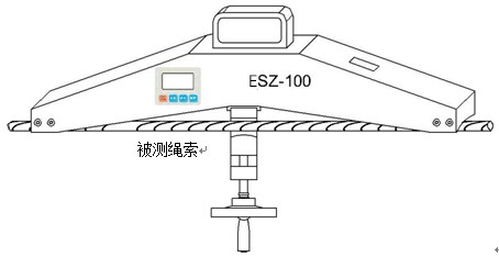
2. Tighten the locking handle and press the measured rope on the positioning block. The displayed value is the actual tension force of the measured rope.
Eleven safety precautions
Precautions
Incorrect operation may damage the instrument or cause serious accidents. This manual indicates important matters to prevent accidents and how to use the instrument. Please read this manual carefully before use, and keep it in a safe place for future reading.
If it is to test the impact load, please choose the model whose MAX load is twice the impact load to be tested.
Cautions
1. Do not use the instrument beyond the MAX range. Doing so may cause damage to the sensor or even an accident.
2. When the test value exceeds the range, the buzzer will beep continuously. In this case, please quickly release the added load or reduce the load.
Safety Precautions
1. Please use the matching charger to charge, otherwise it will cause circuit failure or even fire.
2. Do not use a power supply other than the rated voltage of the charger, otherwise it may cause electric shock or fire.
3. Do not pull out or insert the plug with wet hands, otherwise it may cause electric shock.
4. Do not pull the power cord of the charger to unplug it, otherwise the electric wire will be torn off and get an electric shock.
5. Please clean the machine with a soft cloth. Immerse the cloth in water soaked in detergent and wring it dry before removing dust and dirt.
Note: Do not use volatile chemicals to clean the machine (such as volatile agents, thinners, alcohol, etc.)
6.Do not operate the machine in the following environments
(1) Humid environment (2) Dusty environment
(3) Where oil or chemicals are used (4) Where there are earthquake sources around
7. Please use and store within the specified temperature and humidity range, otherwise it may cause the instrument to malfunction.
8. Do not disassemble, repair or modify the machine yourself. These actions may cause the instrument to malfunction.
9. Other outstanding matters needing attention in safety production.
Other supporting instruments
|
equipment name |
model |
equipment name |
model |
|
Digital push-pull force meter |
HF |
Electric vertical machine |
AEV |
|
Analog push-pull force meter |
NK |
Electric single column vertical machine |
AEL |
|
Digital torque tester |
ANL |
Electric horizontal machine |
AEH |
|
Bottle cap torque tester |
ANL-P |
Spiral roll test machine |
ASC |
|
Pointer torque driver |
ANQ |
Manual horizontal test stand |
AMH |
|
High-speed impact torque tester |
AGN |
Vertical and horizontal test rack |
ASL |
|
Dynamic torque tester |
AND |
Hand pressure type tensile and compression test stand |
AST |
|
Torque Wrench Calibrator |
ANJ |
Spiral tension and compression test stand |
ALX |
|
Torsion spring testing machine |
ANH |
Dedicated testing machine for peeling force |
ABL |
|
Spring tension and compression testing machine |
ATH |
Ball pressure test device |
AQY |
|
Shore rubber hardness tester |
LX |
Motorized hydraulic tension and compression test stand |
ALR |
|
Shore hardness tester bracket |
LAC-J |
Button Tester |
ABQ |
|
Fruit hardness tester |
AGY |
Terminal tensile tester |
ADL |
|
Fruit hardness tester holder |
GYJ |
Rope tension meter |
ASZ |
|
Tonometer |
ATN |
Side tension tester |
HD |