support hotline
0577-57572522
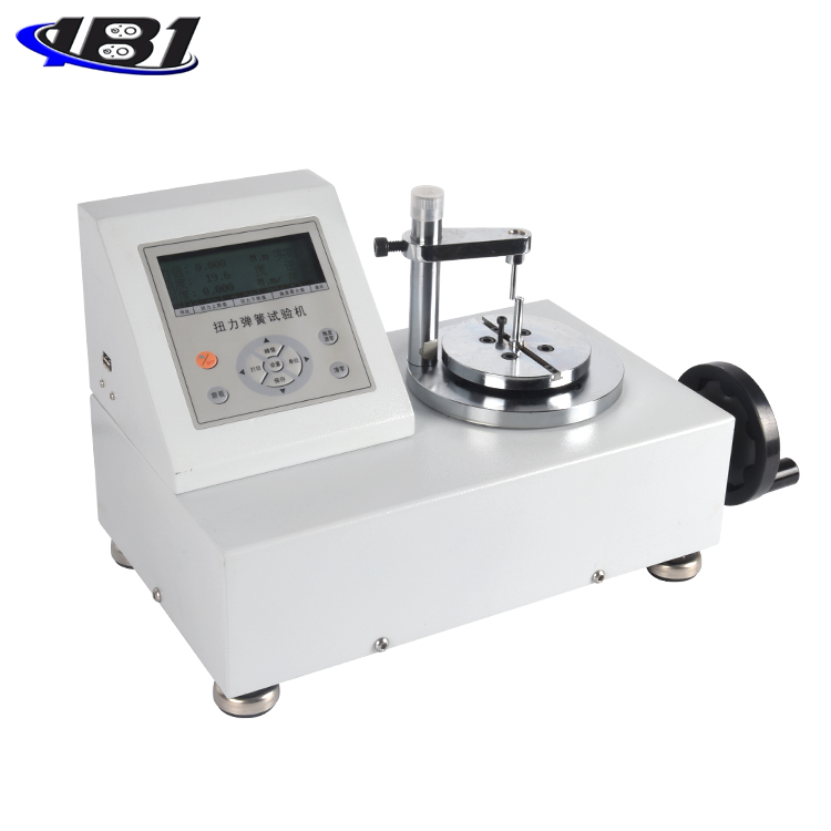
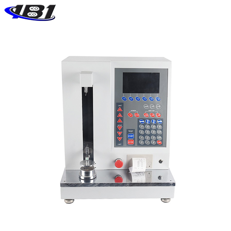
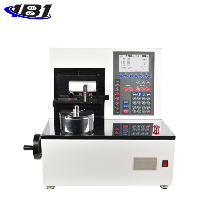
I. Overview
This testing machine is a special instrument for testing the deformation and load relationship characteristics of tensile and compression springs. It is suitable for working load test of tension and compression spring under a certain working length. This test machine uses an advanced, highly integrated, integrated single-chip microcomputer, and a Chinese liquid crystal display. The appearance uses a metal case, which greatly improves the anti-interference ability of the system.
Two: Features
1.Chinese LCD display, better human-machine interface
2.High precision and high resolution
3. Three kinds of measurement units can be selected and converted into each other.
4. The user can set the gravity acceleration of the place of use, which makes the test and unit conversion more accurate.
5. Store 99 sets of test data, you can view and delete the stored data directly on the machine.
6, real-time, peak, automatic peak three modes can be switched at will
7, with customer setting function, free setting of upper and lower limits (corresponding to sound and light alarm), stored value, hold value, automatic peak storage time, automatic shutdown time without operation, etc., freely set
8.Print the stored test data and the maximum, minimum, and average values to make a pass or fail judgment (only with a printer)
9. The communication adopts the MODBUS-RTU standard protocol, and the USB interface is used to better connect with the configuration and PLC.
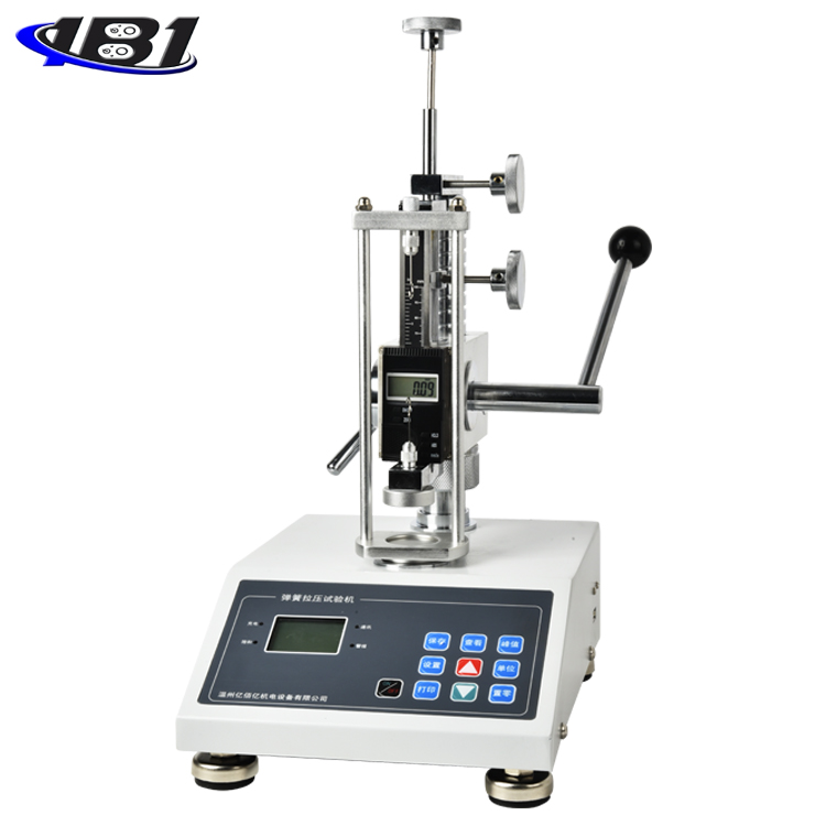
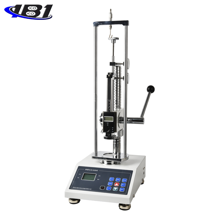
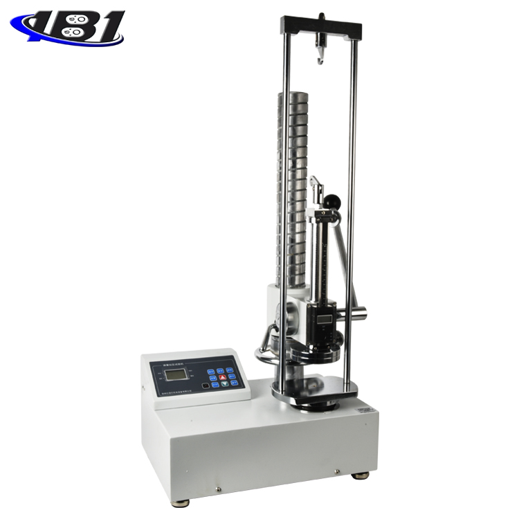
Three: product structure
1.Schematic diagram:
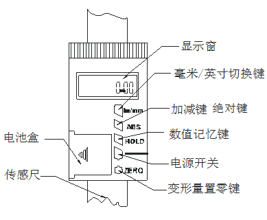
2. Deformation display ruler frame:
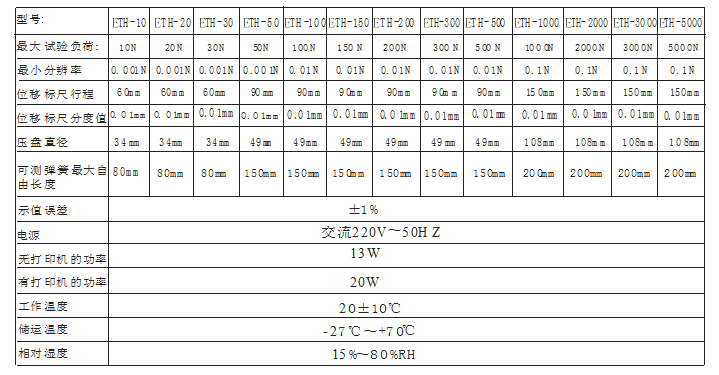
Four: Specifications
Five: display panel
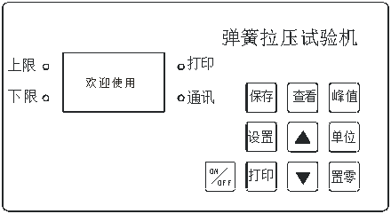
Six: Button description
1. Setting key: The user can enter the setting menu through this key in the measurement interface, and press this key to save the data when setting the data.
2. View key: Use this key to view the stored measurement data during the measurement interface.
3. Peak key: used to switch between three measurement modes: real-time, peak, and automatic peak
4. Save key: used to save the measured data
5. Unit key: used to switch N, Kg, Ib three units
6. Zero-setting key: During real-time measurement, press this key to correct the zero point. During the peak and automatic peak, press this key to clear the peak value and return to zero. When viewing the interface, press this key to clear the current stored measurement value. Press and hold this key to clear all stored measurement values. In the user setting interface, press this key to return to the previous interface without saving data.
7. Print key: In the measurement interface, press this key to print the stored measurement value. (Except those without printing function)
8. Up key: In the user setting interface, press this key to modify the setting items up and down. During parameter setting, press this key to move digits to select the number of digits to be modified. In the viewing interface, press this key to View the previous data.
9. Down key: In the user setting interface, press this key to modify the setting item downwards. During parameter setting, press this key to modify the data at the current position; in the viewing interface, press this key to view the next one. data.
10, ON / OFF key: can be used to turn on and off.
Seven: User operation instructions
1. Startup display
Startup display welcome and manufacturer information
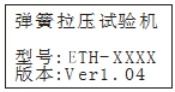
Display product name, model and version information
2. User main interface display
After displaying the start-up display information, enter the main interface of the user and display the following:
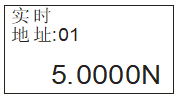
The content displayed in the first line is based on the measurement mode set by the user. It can be divided into three types: real-time, peak, and automatic peak.
The second line shows the data address stored by the user
The third line shows the force value currently measured
3. User setting interface
Press the setting key once, it will display as follows:
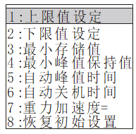
Select the setting item through the up or down key. When the user's setting item is selected, press the setting key to enter the parameter setting interface.
4. Parameter setting interface (the upper limit is set as an example)
In the user setting interface, press the setting key to enter the parameter setting interface, which is displayed as follows:
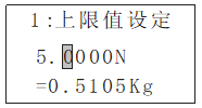
Setting parameter description: Use the up and down keys to shift and modify the data. At this time, press the set key to confirm and save the setting data (such as pressing the zero key to return without modifying the data). The set data cannot exceed the maximum load value.
4.1 Upper limit setting
The user sets the upper limit value, which can be set freely according to the needs. When the upper limit value is reached, the audible and visual alarm is automatically performed.The upper limit value is not higher than the full scale.
4.2 Lower limit setting
The user sets the lower limit value, which can be set freely according to the needs. When the lower limit value is reached, an automatic light alarm is issued.The lower limit value must not exceed the set upper limit value.
4.3 Minimum stored value setting
The user sets the minimum storage value according to the storage needs.Data smaller than this value will not be stored.
4.4 Minimum peak hold value setting
Users need to set freely according to the peak and automatic peak measurement.Data smaller than this value will not be saved by the peak.
4.5 Automatic peak time setting
The user can freely set the time that the peak value needs to be held in the automatic peak measurement state from 1 second to 99 seconds.
4.6 Automatic shutdown time setting
Under no operation state, the automatic shutdown time can be freely set from 1 minute to 99 minutes.
4.7 Gravity acceleration setting
The user can set the gravity acceleration value according to the location of this area.The default value of this machine is 9.794.
4.8 Restore initial settings
Improper user operation or changing data multiple times appears confusing.You can use this setting to restore data from 1 to 7 to the factory state.
5.Instructions for using digital display ruler
①, in / mm: This key is a unit conversion key, which is used to switch between inches and millimeters;
② ABS: This key is an absolute key;
● A certain value is displayed in the display window, and no\"ABS\" character appears on the value, which indicates the normal measurement mode;
● When this key is pressed, the display window will show zero, and the\"ABS\" character appears on the value. At this time, it means the ABS measurement mode, it means the distance is measured from here as the starting point, and the displayed value is the value in the ABS measurement mode. Value
● Until this key is pressed again, no\"ABS\" character appears on the value, indicating that it returns to the normal measurement mode, and the displayed value is the value in the normal measurement mode.
③, hold: This key is a lock memory key, and the value will be locked. If there is no change, press the lock function again to clear.
④ ON / OFF: This key is the on-off key, and the power is switched between on and off;
⑤ ZERO: This key is the zero-setting key, which will clear the displayed value to zero.
Eight. Other function descriptions
1. Printing function description: print data through micro printer
2. Communication: communicate with the host computer via USB. The communication protocol adopts the MODBUS-RTU protocol. The synchronous test function can be connected to a computer test. The computer displays the test force curve chart and the detailed test force record during the test, and can save, print, and perform various analyses.
3. Save data: save the data during measurement with the save key
4. View stored data: View stored data by viewing key
5. Clear stored data: In the viewing interface, clear the current or all stored data by pressing the zero or long press the zero key.
6. Alarm description: When the measured value exceeds the upper limit value or lower than the lower limit value, the buzzer will give an alarm, and the LED lights on the panel will display different colors; when the measured value is lower than the lower limit value, the lower limit indicator light will be displayed. When the measured value exceeds 120% of the maximum load, it may cause damage to the sensor. When the measured value exceeds 150% of the maximum load, it will definitely cause system damage. When \"Overload \" warning prompt appears, the machine enters the automatic protection state, and it must be restarted. If it cannot be measured, press and hold the\"Setting\" key, enter the password: Up and Down keys, and press the Set key to enter the recovery Factory setting interface, select Restore factory settings, and press the set key to restore (if you cannot restore, please contact the manufacturer).
User operation
· Deformation and working load test of tensile spring:
A. Connect the power supply and press the power switch to start the self-test;
B. Press the [Zero Set] key and hear a beep to confirm;
C. Drive the handle upwards, connect the upper and lower spring hook heads, and drive the adjustment handle until the load display is close to the measured spring test load value, and press the zero button for the deformation display.
D. Hang the measured tension spring, pull the drive handle to the required deformation, and read the load display value, which is the working load value of the spring under this deformation.
· Compression spring deformation and working load test:
A. Ibid.
B. Ibid.
C. Drive the handle down to make the upper and lower pressure plates (measurement contacts) contact, drive (adjust) the handle until the load display approaches the test load of the measured spring, and press the zero setting button of the deformation amount display;
D. Place the compression spring under test, turn the handle to press it to the required deformation, and read the load display value, which is the working load value of the spring under this deformation.
Print function:
If you need to print, save the test data and press the print key to print it out.
Note [1]: Since the load measurement sensor of this machine adopts resistance strain type, it will also have a certain deformation when it is under load. In order to reduce the measurement error, the load of the load sensor when the deformation amount is set to zero should be as close as possible to the measured workload value of the measured spring to eliminate the deformation error of the workload sensor. When measuring in general accuracy, the load value when the deformation amount is set to zero can be taken as 10 ~ 15N.
Note [2]: When the deformation amount display is set to zero, the handle is set to zero from the bottom to the bottom. Contrary to the tension spring measurement, the displayed deformation is negative, and the actual reading is taken as its absolute value, that is, the positive value.
· The use of fine adjustment knob:
A. First, connect the fine-tuning knob device to the column firmly, keeping the center between the two on the same line;
B. After confirming that the connection is firmly in the same line with the center, first loosen the left knob to allow the upper knob to move freely, adjust the knob to a suitable position, and then tighten the left knob;
C. Turn on the digital display scale, set it to zero, and then adjust the upper knob according to the needs of the test, you can get a small displacement variable, which meets the requirements of precise measurement;
D. Note: The ETH series spring testing machines provided by our company are roughly divided into three ranges: small, medium, and large. There are no fine-tuning knobs for a large number of ranges.
Ten, matters needing attention
Incorrect operation may damage the instrument or cause serious accidents. This manual points out important matters to prevent accidents and how to use the instrument. Please read this manual carefully before using it, and keep it in a safe place for future reading.
· Precautions for use
A. The environment should be kept clean to avoid liquids, iron filings and other substances from invading the deformation amount and the load sensor components, and damaging the electronic components.
B. Please use a soft cloth to clean the instrument, immerse the cloth in water soaked with detergent, wring dry, and then remove dust and dirt.
Note: Do not use volatile chemicals to clean the instrument (such as volatile agents, thinners, alcohol, etc.)
C. Do not operate the machine in the following environments
(1) Humid environment
(2) Dusty environment
(3) Where oil or chemicals are used
(4) Where there are earthquake sources around
D. Deformation sensing calipers and sliding rack surfaces can be cleaned with clean gasoline, and can be lubricated with a small amount of watch oil. Do not use acetone or alcohol.
E. Unused for a long time, unplug the power plug, and do dustproof and moistureproof treatment.
Eleven, failure and maintenance
|
Phenomenon |
the reason |
Repair |
|
Deformation display only shows 000.00 or IN00.000 |
Two function button reed short circuit |
Remove the protective frame to make the button reed ideal |
|
Deformation display function buttons do not work |
Press the function button too hard to deform the reed |
Remove the protective frame to make the button reed ideal |
|
Deformation of full length after using for a period of time ≤0.1mm |
Deformation inside the sensor |
Remove the protective frame, remove the display accessories, spray the sensor surface with clean compressed air ≤5kg / cm, and wipe with a little gasoline to remove dirt. |
|
No load display |
1. The power is not connected. 2. The switch button is not touching. |
1. Connect the power supply. 2. Press the switch again. |