support hotline
0577-57572522
I. Overview
1.1 Main uses and scope of application
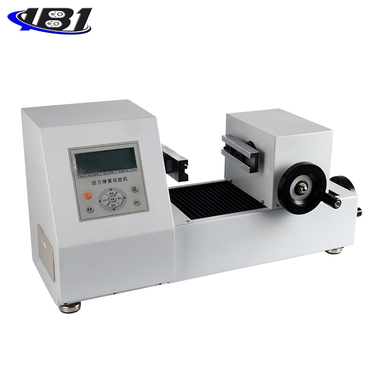
Fully automatic spring testing machine is a new type of spring testing machine that combines advanced electronic technology and efficient and precise mechanical transmission. Technical requirements made. Equipped with high-precision sensors for precise loading and positioning. It is mainly applicable to the tensile, compression, stiffness, fatigue and other tests of elastic devices such as springs, rubbers, and reeds under a certain working length. Widely used in spring manufacturing companies and users.
1.2 Product Features
1.2.1 Can measure the tension, pressure, stiffness, displacement of the spring, and display the date and number.
1.2.2 Three units display: N, Kg, Lb
1.2.3 Can specify 1, 2, 3, 4, 5 segments.
1.2.4 There are two modes: long-charge and long-charge.
1.2.5 Adjustable sampling rate, multiple measurement methods can be selected
1.2.6 The use of large-scale integrated circuits improves the test accuracy, and the human-machine Chinese dialogue is intuitive and clear.
1.2.7 A special spring detection program designed in accordance with national standards has high efficiency, complete functions and convenient operation.
1.2.8 Considering the principle and the program software, the accurate measurement range of the measurement range has been improved.
1.2.9 It is suitable for batch testing and sorting of springs on the production line, as well as precision sampling inspection in the laboratory.
1.2.10 It has program-controlled and mechanical two-level limit protection. Pre-loading and deflection compensation correction ensure accurate measurement.
1.3 Specifications
|
model |
ETSM-10 |
ETSM-20 |
ETSM-50 |
ETSM-100 |
ETSM-200 |
ETSM-500 |
|
Load capacity |
10N |
20N |
50N |
100N |
200N |
500N |
|
Minimum division value |
0.0001N |
0.001N |
0.001N |
0.001N. |
0.01N |
0.01N |
|
Unit selection |
N, Kg, g, lb |
|||||
|
Precision |
± 0.5% |
|||||
|
Length (displacement) accuracy |
0.01mm |
|||||
|
Stroke |
200mm |
|||||
|
Speed range |
1-500mm / min |
|||||
|
Standard platen diameter |
φ20mm |
φ60mm |
||||
|
Manual key movement |
1mm, 0.1mm, 0.01mm |
|||||
|
Test selection |
Compression, stretching |
|||||
|
Spring test options |
1.Measure the load by setting the length 2.Measure the length by setting the load 3. Set the deformation to measure the load. 4. Set the load to measure the load. |
|||||
|
Dimensions |
450mm * 380mm * 550mm |
|||||
|
weight |
About 60kg |
|||||
|
power supply |
220V 0.5A |
|||||
|
Machine characteristics |
1.Can test free length automatically 2, load sensor and tension spring test hook deformation compensation automatically 3.Load sensor overload protection function and emergency stop function 4.Can connect micro printer |
|||||
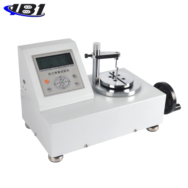
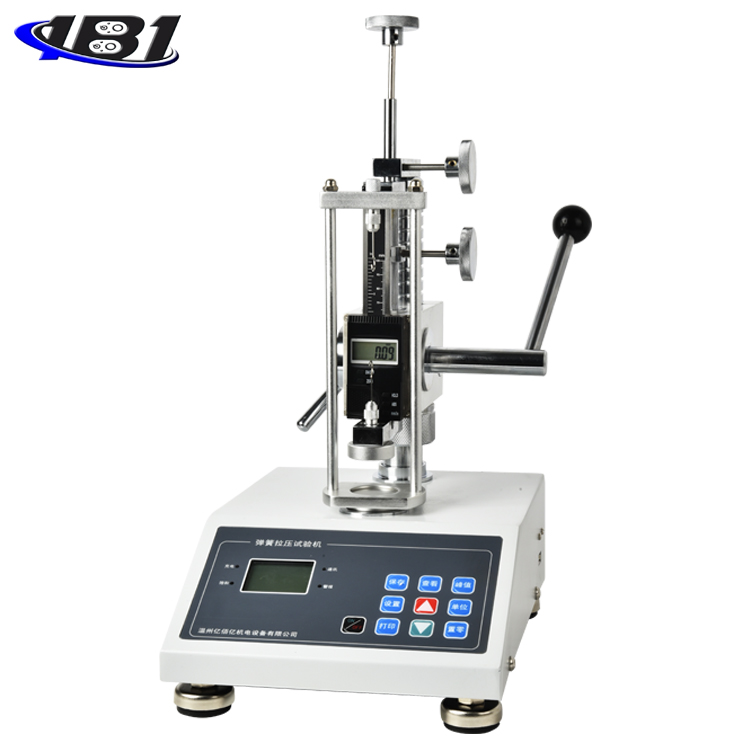
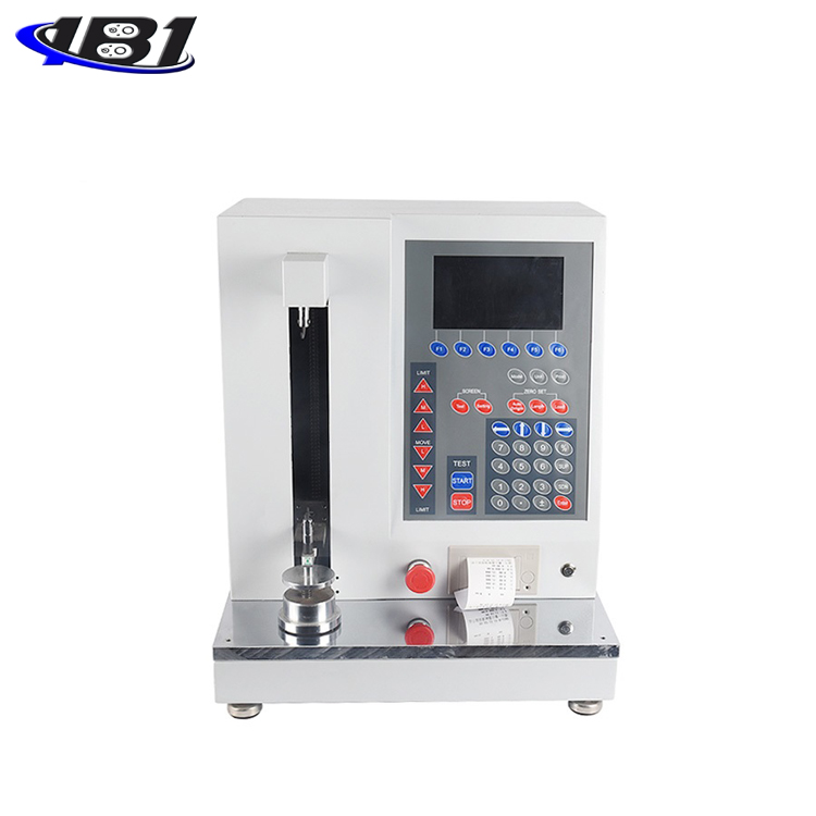
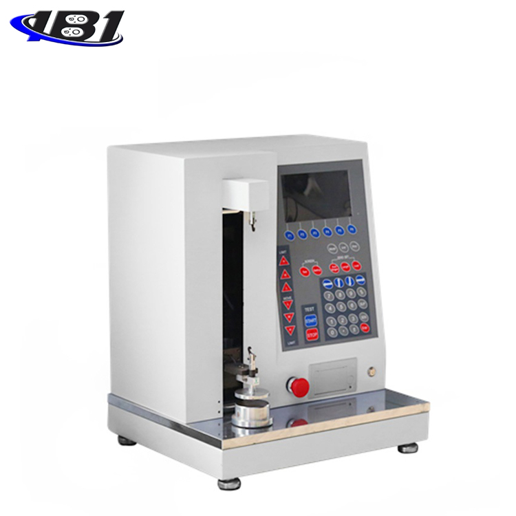
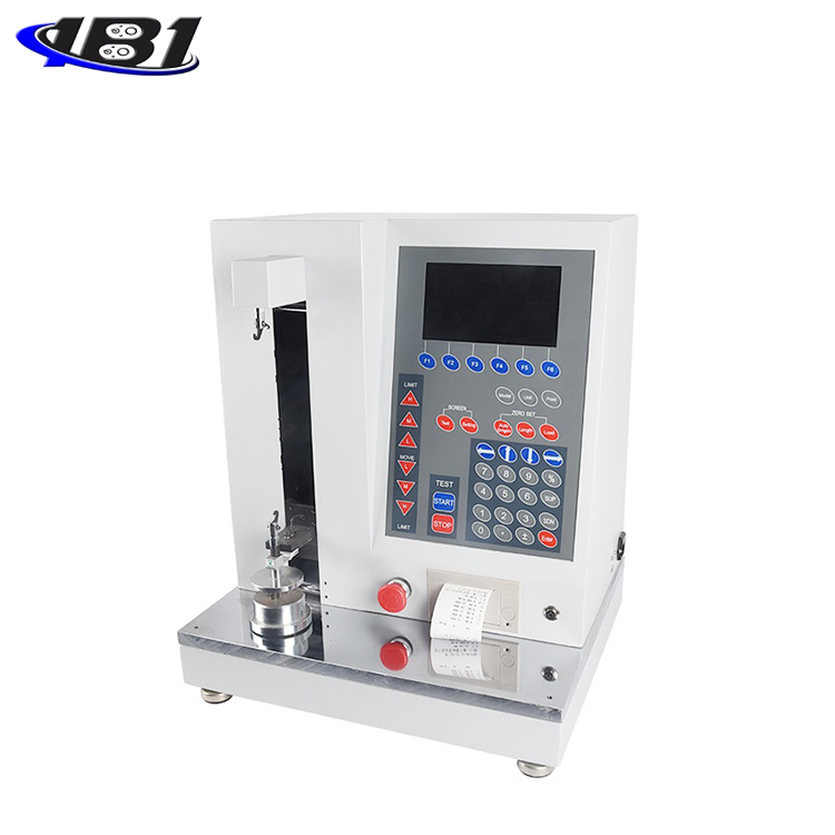
Overall product structure
2.1 outline structure

2.2 LCD screen function

2.2.1 Function keys: The six function keys F1 ~ F6 are common to all interfaces of the instrument and correspond to the keys at the bottom of the screen after power-on.
2.2.2 High-speed / medium-speed / low-speed up, low-speed / medium-speed / high-speed down: these 6 keys have two functions of short press and long press. The requirement is to manually adjust the position of the measuring block. For example, short-press high-speed upward means that the measurement block runs upward at a higher speed of 1mm, medium-speed upward means that the measurement block runs upward at a medium speed of 0.1mm, and low-speed upward means that the measurement block has been run upward by 0.01mm at a low speed.
And long pressing these keys can make the measuring block run upward at a certain speed, the stop key is pressed, or the protection mechanism is activated. The high, medium and low speeds correspond to 100mm / min, 10mm / min and 1mm / min respectively. The function of the down button is the same as the up button.
2.2.3 Unit key: Unit switching.
2.2.4 Print key: It is valid in real-time measurement interface and data saving display interface. Press the print key on the real-time measurement interface to print the currently displayed segment data. There are two printing methods on the saved data interface. One is to print the current set of data, or a set of data for all repeated measurements.
2.2.5 Setting key: Enter the system setting interface.
2.2.6 Auto Origin: Press this key, the spring will return to the free state and record the free length.
2.2.7 Position Clear: This key has two functions: short press and long press. Short press is used to clear the position display. When the position display is zero, press this key again to display the absolute position value again. Long press the zero button on the position, you can calibrate the position. For the position calibration, you must first select the spring mode, compression and stretching. The compression mode calibration is to calibrate the position of the measuring block to the bottom platform, and the stretching mode. That is, position calibration needs to be performed with the calibration hook to determine the absolute position during stretching. If the absolute position is not accurate due to abnormal power failure or other reasons, you can use the position calibration of the compression mode to calibrate to obtain the corresponding absolute position.
2.2.8 Force value reset: Press this key to clear the displacement value. The force value clearing is effective only when the motor is stopped.
2.2.9 Start key: press this key to start the test.
2.2.10 Stop key: Press this key to terminate the test.
2.2.11 Up / Down / Left / Right: Used to select the number of digits for the spring setting.
2.2.12 Numeric keys: Used for spring setting.
2.2.13 Switch / Reverse Switch / Confirmation Key: Used to select and confirm the controls in the interface.
Use and operation
3.1 Operation and instructions in use
3.1.1 Measurement interface

a. The real-time measurement interface mainly displays the current real-time displacement and force values. If it is in the measurement process, it records the test point data, and also displays the current spring number and repeat number.
b. In the real-time measurement interface, you can switch the spring type, measurement mode, number of measurement segments and units; the system will save the corresponding settings after the switch.
c. Spring type: The compression spring can only be set as compression, and the tension spring can only be set as extension.
d. Measurement mode: It is divided into load-length and long-charge. The difference between the two modes is that the reference is different. Long-charge records the spring position according to the corresponding force value. Force value.
e. Number of measurement segments: Test the corresponding spring test points according to the set number of measurement segments. One segment is to find the force value or position of the first test point.
Real-time spring measurement, depending on the type, and selected displacement (relative and absolute) mode. The setting value of its operation measurement will also be different.
Taking a compression spring as an example, in the load-length mode, if the relative displacement mode is selected, then the reference displacements of the segments 1 to 5 need to be increased, otherwise it will not work properly. However, if the absolute displacement mode is selected, then the base equipment displacements of segments 1 to 5 need to be reduced or else it will not work properly.
At the same time, the final position reached by the measurement block cannot exceed the logical limit position of the measurement block, otherwise it will not work properly.
3.1.2 System Settings
System settings include spring parameter settings, operating parameters, time settings, and factory reset.
3.1.3 Spring parameter setting

a. Test number: The maximum test number can be set to 32. After pressing \"Add \", the test number is added to one group. Enter the spring parameters to be tested and press \"Save \". As shown below:

b. Number of repetitions: The maximum number of repetitions can be set to 99. After pressing\"Add New\", the test number is increased by one group. Press \"SUP \" and \"SDN \" and move the cursor to \"Repeats \" , Enter the required value, and press \"Save \".
c. Running speed: The running speed during the spring test, expressed as mm / min. The larger the value, the faster the speed.
d. Displacement (mm): the position of the point during the spring test period.
e. Reference value: the force value corresponding to the segment point.
f. Tolerance: The setting for determining the qualified range of the spring can be set from 0% to 99%. For example, when set to 1%, the upper limit value is 4.95 and the lower limit value is 5.05. When the spring value is within the upper and lower limits, Inside is qualified.
g. Upper limit value / lower limit value: These two parameters do not require user input. The instrument will automatically obtain these two parameters based on the reference value and tolerance.
After setting the spring parameters, modify the value of the selected number to select the spring setting. Modify the selected number and exit.
3.1.4 Operating parameters

a. Acceleration / deceleration setting: Acceleration / deceleration setting refers to the acceleration setting of the upper block during measurement. When it is set to 0, it is off; when it is set to 1, it is on. The acceleration setting and the measurement point stop setting conflict. The acceleration / deceleration setting is effective only when the measurement point stop setting is set to 0.
b. Measurement point stop setting: The measurement point stop setting refers to the stop setting of the instrument at each segment point during measurement. When it is set to 0, it is off; when it is set to 1, it is on. In the on state, if the number of segments is set to 5, the instrument will stop once at these 5 segment points during measurement; if in the off state, the instrument will not stop at the segment points during measurement.
c. Continuous test setting: Repeat the test setting. When it is set to 0, it is off; when it is set to 1, it is on.
d. Starting speed: The starting speed setting is only valid when the acceleration / deceleration setting is on. The starting speed can be set to 1 to 5. When set to 1, the acceleration is from 1mm / min to 100mm / min during measurement. The larger the value is set , The faster the startup speed. The speed setting unit is mm / min. The startup speed cannot be set to 0.
e. Without the first segment stiffness: When the first segment stiffness is set to 1, it is turned on. For example, if five segments are set, the instrument will not calculate the first segment stiffness when calculating the average stiffness. If it is set to 0, then Is off.
f. Sampling rate: The number of samples per second of the instrument, which can be set from 1 to 100.
g. Automatic zero-speed: The high-speed setting of the automatic origin can be set from 1mm / min to 100mm / min. After pressing the automatic origin button during measurement, the spring will return to a position relatively close to the origin with the set automatic zero-speed.
h. Automatic zero low speed: Automatic zero low speed is a value set on the basis of automatic zero high speed. It can be set from 1mm / min to 10mm / min. When the spring returns to a position relatively close to the origin, the automatic zero low speed starts. To make the spring return to the original position more accurately.
i. Zero high ratio / zero low ratio: These two parameters are the determination of the force value of the automatic origin. For example, the zero high ratio is set to 200, that is, the force value is full scale * 200/10000, which is 2% of full scale. The zero low ratio is set to 3, that is, this force value is full scale * 3/10000, which is 0.03% of full scale. After starting the automatic origin, when the force value is close to 2% of the full scale, the instrument will stop at the position of the automatic origin according to the low-scale force value after a few seconds of pause of this force value.
j. Limit protection switch: physical limit switch protection, when it is set to 1, it is on; when it is set to 0, it is off. This function is not recommended to be set to the off state. However, due to the limit protection of the spring machine, the default state of the measuring disc cannot run below the bottom plane. If the measured spring is short, you can consider turning off the limit protection to achieve the measuring disc bottom.
k. Displacement absolute mode: When set to 1, it is displacement absolute mode; when it is set to 0, it is displacement relative mode. For relative measurement mode and absolute measurement mode, it is the difference between setting the deformation amount and setting the length. The relative measurement mode is how many millimeters are stretched or compressed, while the absolute mode is expressed as how many millimeters are stretched or compressed.
Relative measurement mode, the displacement required to set the number of spring segments, LENGTH1
At the same time, the force value setting is also required, FORCE1
The absolute measurement mode will have different setting parameters for different spring types.
Compression spring, LENGTH1> LENGTH2> ...> LENGTH5
Tension spring, LENGTH1
3.1.5 Time setting

Time setting is used to set the time displayed on the measurement interface and print time
3.1.6 Restore factory settings
Press this key, the instrument restores the factory settings and restarts automatically
3.2 Operation steps
3.2.1 Make sure the power cord is connected.
3.2.2 Turn on the power switch.
3.2.3 Select spring type, unit, measurement mode and number of measurement segments.
3.2.4 Enter the spring parameter setting and operation parameter setting, enter the spring parameters, and exit after saving.
3.2.5 Back to the measurement interface, press \"START \" to start the test, and then press \"Print \" to print the measurement data.
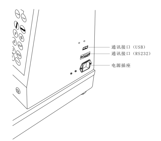
3.3 Data export
3.3.1 Using the communication interface, real-time measurement data can be exported through the communication protocol provided by the Division.
Fourth, daily maintenance and maintenance
4.1 The environment shall be kept clean to prevent liquids, iron filings and other substances from entering the instrument and damaging the electronic components.
4.2 Please clean the instrument with a soft cloth, immerse the cloth in water soaked with detergent, wring it dry, and then remove dust and dirt.
Note: Do not use volatile chemicals to clean the instrument (such as volatile agents, thinners, alcohol, etc.)
4.3 Do not operate this machine in the following environments
a, humid environment
b. Dusty environment
c. Where oil or chemicals are used
d. Places with earthquake sources around
4.4 When not in use for a long time, unplug the power plug, and do dustproof and moistureproof treatment.
Five, random attachments
|
1 |
Machine |
1 set |
|
2 |
power cable |
1 |
|
3 |
Manual |
1 serving |
|
4 |
Certificate of conformity |
1 serving |
|
5 |
Warranty Card |
1 serving |
|
6 |
Standard hook |
1 |