support hotline
0577-57572522
I. Use
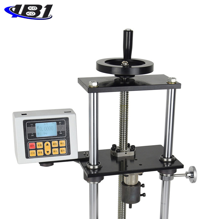
Torque driver verification instrument is an intelligent multifunctional measuring instrument designed and manufactured for testing and detecting various torque drivers. It is mainly used to detect and correct various torque screwdrivers. Various products involve the test of tightening force and the torsional destructive test of parts. It has the characteristics of simple operation, high precision, and full functions. It is widely used in various electrical, light industry, machinery manufacturing, scientific research institutions and other industries.
Second, the functional characteristics
1. High precision, high resolution, fast sampling speed, full screen display.
2. High precision torque sensor with torque direction display.
3. Setting of upper and lower limits.
4. The three types of units can be converted to each other for selection (N · m, kgf · cm, Ibf · in).
5, real-time, peak, automatic peak three modes can be switched at will.
6. It adopts USB interface to communicate with PC. It may be connected to a computer for synchronous test. The computer displays the test force curve chart and detailed test force record during the test.
7, peak hold function, automatic peak function, automatic peak value display time free setting function.
8, large storage capacity, can save 999 sets of test data.
9. Automatic shutdown function without operation, time can be set freely.
Specifications
|
model |
EQJ-2 |
EQJ-5 |
EQJ-10 |
EQJ-20 |
|
|
Measuring range / division |
N.m |
2.0000 / 0.0001 |
5.0000 / 0.0001 |
10.000 / 0.001 |
20.000 / 0.001 |
|
Kgf.cm |
20.421 / 0.001 |
51.052 / 0.001 |
102.10 / 0.01 |
204.21 / 0.01 |
|
|
Ibf.in |
17.724 / 0.001 |
44.311 / 0.001 |
88.62 / 0.01 |
177.24 / 0.01 |
|
|
Precision |
± 1% |
||||
|
power supply |
7.2V 1.2V × 6 Ni-MH battery pack |
||||
|
Charging time |
10 ~ 12 hours |
||||
|
Battery continuous use time |
About 10 hours |
||||
|
Battery Life |
≧ 300 times |
||||
|
size |
260mm × 300mm × 620mm |
||||
|
Net Weight |
32KG |
||||
|
charger |
Input: AC 220V 50HZ Output: DC 12V 500mA |
||||
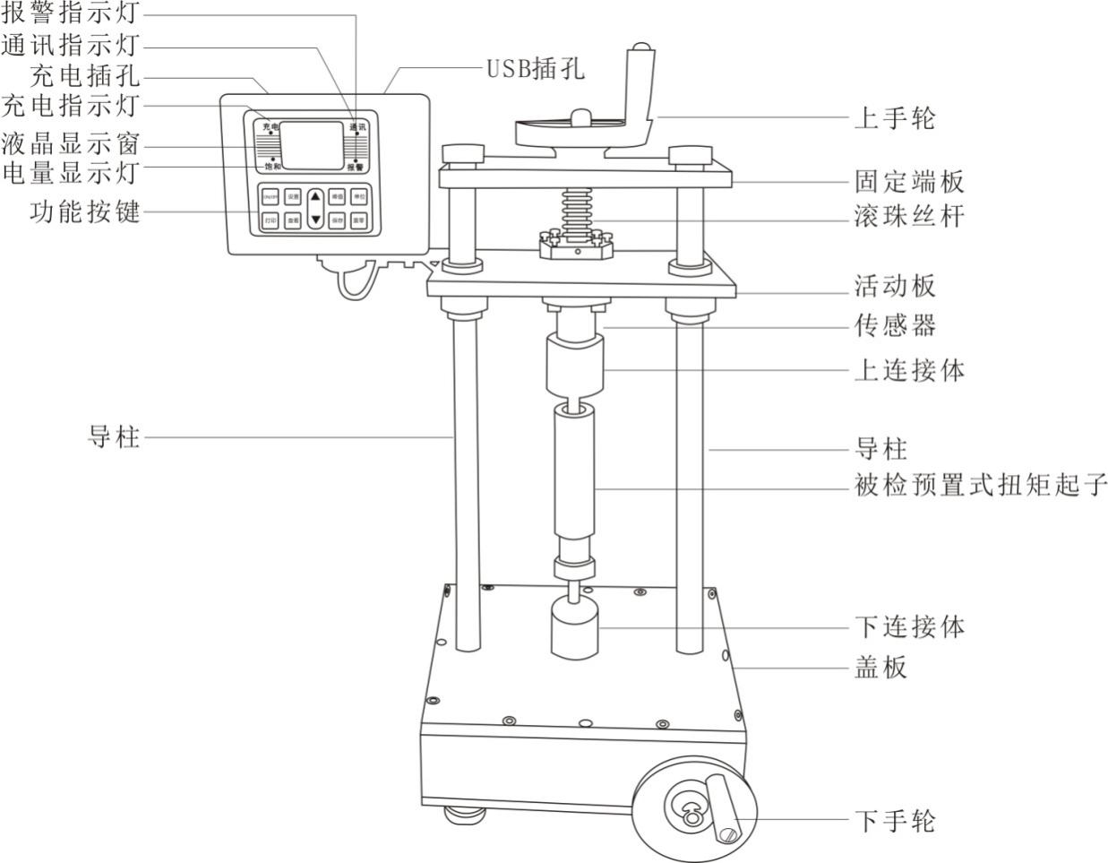
Fourth, the name and function of each component
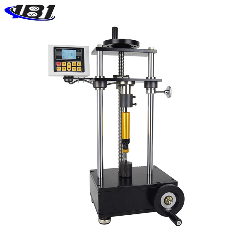
1.LCD display window
a, boot display
Startup display manufacturer information Welcome your use and display product model

b. User main interface display
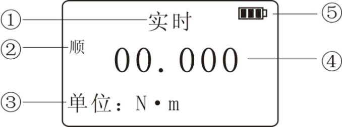
① Measurement mode: There are three modes: real-time, peak, and automatic peak. Users can choose freely according to their needs.
② Measure the twist direction: \"CW \" means clockwise, \"Counter \" means counterclockwise.
③ Measurement unit: N · m, Kgf · cm, Ib · in.
① Measure the force value.
② Battery level display: When the battery level is low, it displays \" \", You need to charge.
1.Indicator
① Charging: When charging with the matching power adapter, the charging indicator lights up red.
② Saturation: When fully charged with the matching power adapter, this light is green.
③ Communication: When connected to the computer, the communication lamp lights up green.
④ Alarm: upper and lower limit alarms. When the measured force value is higher than the upper limit value, the alarm lamp lights up red and the buzzer alarms; when the measured force value is lower than the lower limit value, the alarm lamp lights up green and the buzzer alarms.
2. Function buttons
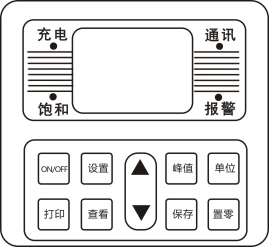
\"ON / OFF \" key: Power switch, turn on and off.
\"Print \" key: used on an instrument equipped with a printer, press this key to print out the measurement data stored inside the instrument (except for those without a print function, this instrument has no print function).
\"Setting \" key: Users can enter the setting menu by this key when in measurement mode.
\"View \" key: In the measurement mode, you can view the stored measurement data by pressing this key, and press 1 again to return to the measurement mode.
\" \"Key: In the user setting interface, press this key to modify the setting items up and down. During parameter setting, press this key to modify the data in the current position; in the viewing interface, press this key to view the previous data.
\" \"Key: In the user setting interface, press this key to modify the setting items downwards. During parameter setting, press this key to modify the data in the current position; in the viewing interface, press this key to view the next data.
\"Peak \" key: used to switch between three measurement modes: real-time, peak, and automatic peak.
\"Save \" key: used to save the measured data.
\"Unit \" key: Used to switch between N · m, Kgf · cm, and Ib · in.
\"Zeroing \" key:
① During real-time measurement, press this key to correct the zero point.
② During peak and automatic peak, press this key to clear the peak and return to zero;
③ When viewing the interface, press this key to clear the current stored measurement value, and long press this key to clear all stored measurement values.
④ In the user setting interface, press this key to return to the previous interface without saving data.
3. Charging jack: used to connect to external power supply for charging.
4. USB jack: USB interface output for connecting to a computer.
V. Working environment
1. Operating temperature: -10 ℃ ~ 40 ℃.
2. Operating humidity: ≤90% RH.
3. There is no vibration source and no corrosive environment around.
Operation steps before testing
1. Before using the torque screwdriver tester, check whether the power of the instrument is sufficient. If the power is insufficient, charge it first (you can also use the instrument when charging).
2. Under normal circumstances, turn on the power switch and the displayed value is zero. If it is not zero, press the \"Clear \" key to clear the value.
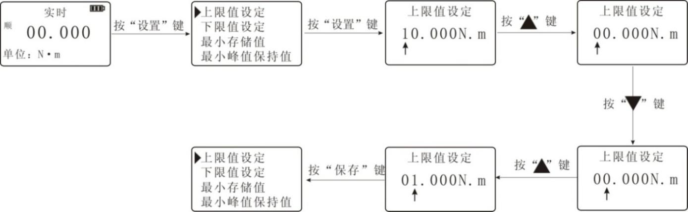
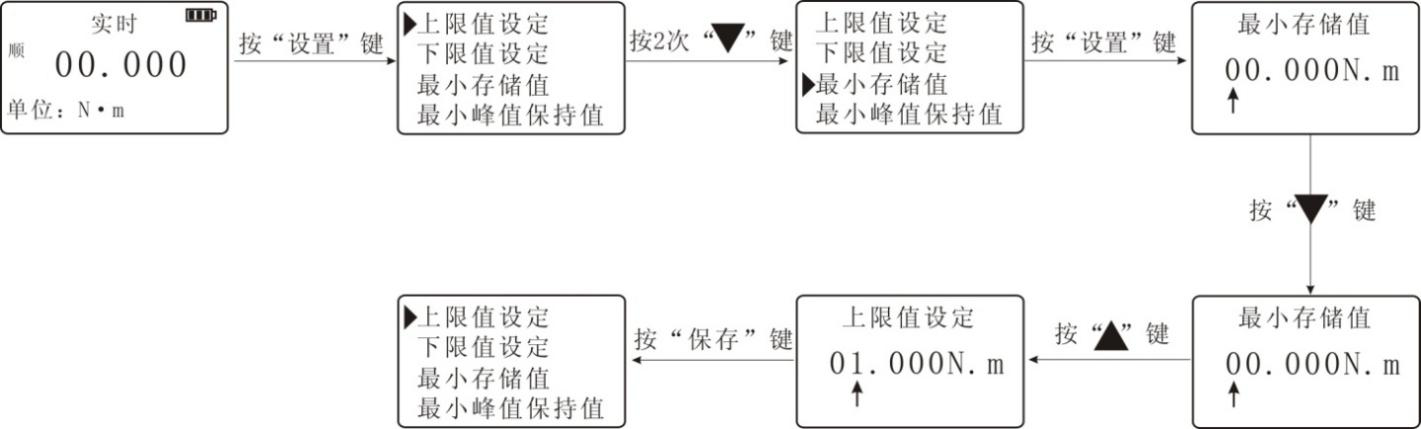
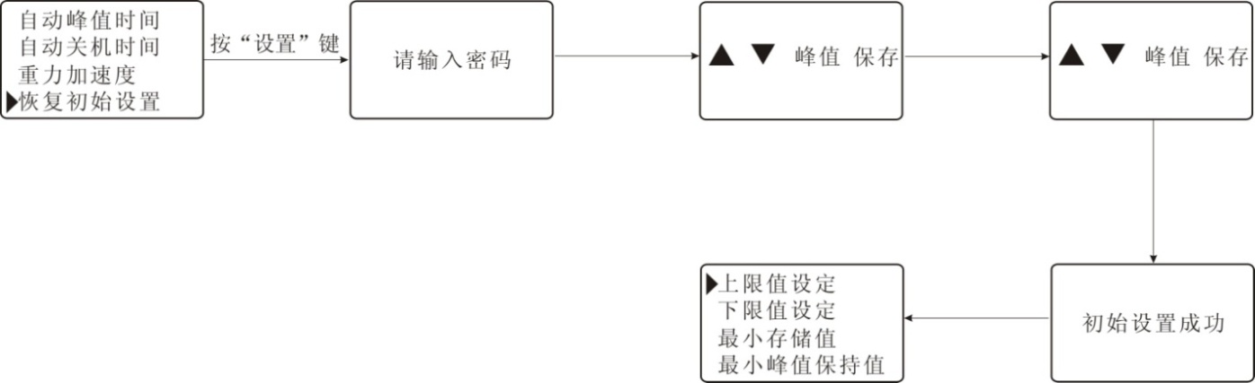
3. Before testing, you need to set the upper and lower limits, minimum storage value, minimum peak hold value, automatic peak time, automatic shutdown time, gravity acceleration, etc. The specific operation steps are as follows:
a. Upper limit value setting: The user sets the upper limit value, which can be set freely according to the needs. When the upper limit value is reached, an audible and visual alarm is automatically issued. The upper limit value is not higher than full scale. On the measurement interface, press the\"Settings\" key to enter the setting interface, select \"Upper limit value setting\", press the\"\" Setup\"\" key to enter the\"Upper limit value setting\" interface, and press \"\"Key to change the value, press \"\"Key to change the number of digits, set the required value, press \" Save \"key to return to the setting interface, the lower limit setting is the same as above. (The maximum value for the upper and lower limits is 10, the minimum is 0)
b. Lower limit value setting: The user sets the lower limit value, which can be freely set as required. When the lower limit value is reached, an automatic light alarm is issued. The lower limit value cannot be higher than the set upper limit value. Specific settings are set as the upper limit.
c. Minimum storage value setting: The user sets the minimum storage value according to the storage needs, and data less than this value is not saved by the peak value. Select \"Minimum Stored Value \", press \"Settings \" key to enter, also use \"\"Key and \"\"Key to set the required value, press \" Save \"key to return to the setting interface (the minimum stored value is set to a maximum of 10 and a minimum of 0).
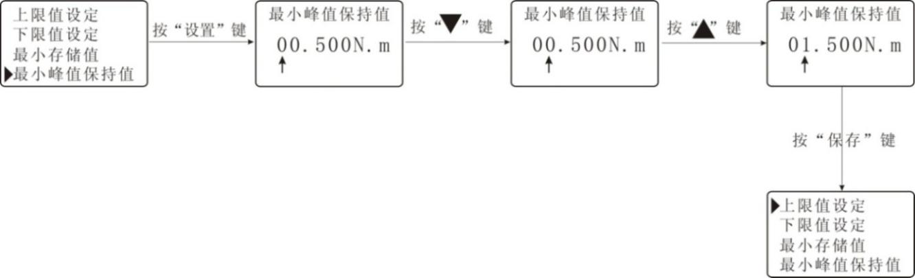
d. Minimum peak hold value setting: The user needs to set freely according to the peak value. The automatic peak measurement needs to be set freely. Data less than this value is not saved by the peak value. Enter the \"Minimum Peak Hold Value \" interface, also use \"\"Key and \"\"Key to set the required value, press \" Save \"key to return to the setting interface.
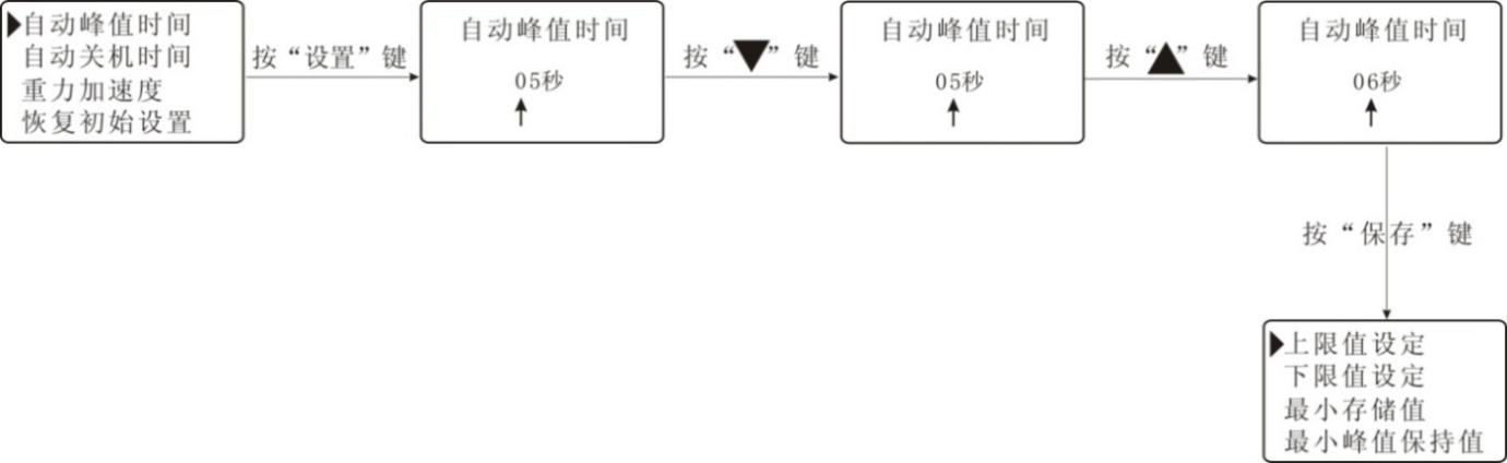
e. Automatic peak time setting: The user can freely set the time that the peak value needs to be held in the automatic peak measurement state from 1 to 99 seconds. Enter the \"Automatic Peak Time \" interface, also use \"\"Key and \"\"Key to set the required value, press \" Save \"key to return to the setting interface.
f. Automatic shutdown time setting: In the non-operation state, the automatic shutdown time can be freely set from 0 minutes to 9 minutes (when set to 0, it means to cancel the automatic shutdown). Enter the \"Automatic shutdown time \" interface, use \"\"Key to set the required value, press \" Save \"key to return to the setting interface.

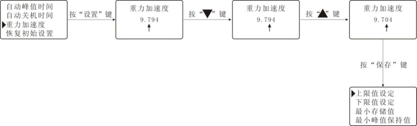
g. Gravity acceleration setting: The user can set the gravity acceleration value according to the location of the area. The default gravity acceleration value of this machine is 9.794). Enter the \"gravity acceleration \" interface, use \"\"Key and \"\"Key to set the required value, press \" Save \"key to return to the setting interface.
h. Restore the initial settings: Improper user operations or multiple changes to the data appear confusing. You can use this setting to restore the data from 1 to 7 to the factory state. Enter the \"Initial Settings \" interface, and enter the password to complete the setting.
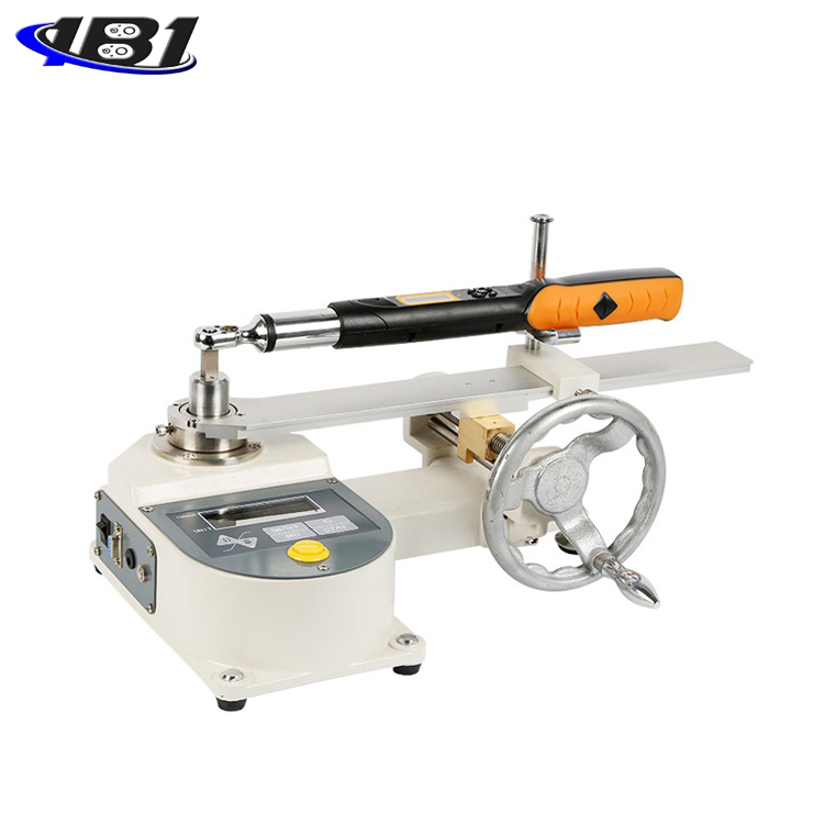
Seven, test steps
1. Adjust the torque value of the tested preset torque driver to a preset value.
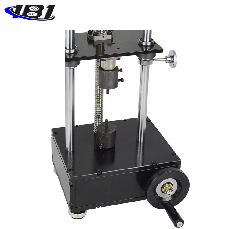
2. Shake the upper hand wheel to adjust to the proper height, put the top of the screwdriver into the upper connector
3 Shake the lower hand wheel to adjust the lower connecting body to a proper angle, put the bottom end of the screwdriver in and fix it.
4. Switch on and select the unit and measurement mode as required. (Generally select the peak measurement mode)
5. Turn the lower hand wheel clockwise to apply force. The value displayed on the screen of the instrument is the measured torque value.
USB output
The instrument communicates with the host computer via USB. The communication protocol is MODBUS-RTU protocol. The specific connection method between the instrument and the software is as follows:
1. Connect the instrument and the computer with a USB data cable.
2. Turn on the power of the instrument so that the instrument is in the measurement interface.
3. Put the supplied CD-ROM into your computer's CD-ROM drive and open the serial port software path: CD-ROM \ aliyiqi \ AutoTest.exe.
4. Click the\"System\" button at the bottom of the software window to pop up the\"System Settings\" dialog box. Select the corresponding serial port in the communication port from the computer. The specific operation steps are as follows:
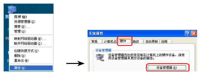
① Right-click \"My Computer \" Select \"Properties \", select \"Hardware \" option bar in the pop-up \"System Properties \" dialog box, and then click the \"Device Manager \" button (as follows (Shown in the figure):
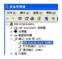
② In the pop-up\"Device Manager\" dialog box, check the sub-item serial number of the port item class (as shown in the figure below):
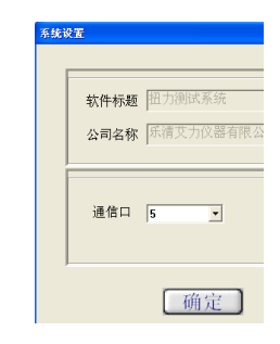
③ Return to the\"System Settings\" dialog box popped up by the software, select the corresponding serial port number in the communication port (the analogy is\"\" 5 \"), and then press OK, as shown in the figure below:
④ Close the software and double-click AutoTest.exe again to check whether the serial port is connected. There are several ways to check it: Apply a point force on the sensor of the instrument and check whether the torque value at the top of the software window corresponds to the jump. A bounce indicates that it is connected, otherwise the opposite is true.
① Click the\"Settings\" button at the bottom of the software window to bring up the\"Parameter Setting\" dialog box and fill in the corresponding data according to the test needs. The specific parameter size is as described in step 6-3-b. After filling it out, just press the\"OK\" button. After the setting is successful, the data displayed at the bottom of the software window will change accordingly.

② Make sure the serial port is connected first, and press \"Start \" button for synchronous test.
⑦ After the test is completed, press the\"Stop\" button and click\"Save\" or\"Stop\". Save to save the test curve into the software, and vice versa when stopped.
⑧Software interface introduction:
a. There is a torque value display area, a time display area and the number of test times at the top.
b. On the left, there are upper limit line, lower limit line, indication line, specification display, display curve, clear curve and derived curve.
Upper limit line: When the square in front of the upper limit line is checked, the curve display window has a horizontal line showing the upper limit torque value.
Lower limit line: When the square in front of the lower limit line is ticked, the curve display window has a horizontal line showing the lower limit torque value.
Instruction line: the mouse is in the shape of a cross in the curve display window, and the torque of the cross mouse position is corresponding to the torque
Both the value display area and the time display area change accordingly.
Show curve: Click this button to pop out the\"Select Curve\" dialog box, select the test items you want to display, and then select
The number of tests to display.
Clear curve: Click this button to erase the currently displayed curve instead of deleting it from the software.
Off.
Export curve: Click this button to pop up the \"Export curve \" dialog box, select the format of the curve picture you want, select
After the path of the curve picture is saved, press OK.
c. There are settings, start, stop, report, system, help, delete and exit buttons below.
The settings, start, stop, and system buttons have been described in the front.
Report: Click this button to pop up the\"Curve data selection preview\" dialog box, select the sampling point frequency first
Then select the test items you want to display and the number of tests you want to display. Finally click the\"Execl\" button.
Nine, matters needing attention, maintenance and repair
1. Don't test the torque overload. Be sure to test the torque within the test range of the instrument, otherwise it will damage the instrument and may cause danger.
2. Do not tap the LCD screen and place objects on the LCD screen.
3. Do not press the function keys with nails, sharp objects or pointed objects.
4. Do not use the instrument in the place where water, oil or other liquids are splashed. Store the instrument in a cool, dry and vibration-free place.
5. Do not open the small cover on the back, nor can you adjust the trimmer resistor inside.
6. Do not loosen the fixing screws of the instrument.
7. Please use the matching power adapter to charge, otherwise it will cause circuit failure and even fire.
8. Insert the AC power adapter completely into the socket before using it. Loose plugs may cause short circuits and cause electric shock or fire.
9. Do not use a power supply other than the rated voltage of the power adapter, otherwise it may cause electric shock or fire.
10. Please do not pull out or insert the plug with wet hands, otherwise it may cause electric shock.
11. Please use a soft cloth to clean the machine, immerse a dry cloth in water soaked with detergent, wring it dry, and then remove dust and dirt. Do not use chemicals that emit easily, such as volatile oils, thinners, alcohol, etc.
12. Handle gently during use and handling.
13. Do not disassemble, repair or modify the machine yourself. These actions may cause permanent failure of the instrument.
14. If any trouble occurs, please contact the place of purchase or the company.
15. Within one month from the date of sale of this product, product quality problems have occurred under normal use and no damage to the appearance. The customer should bring the original sales invoice, valid warranty card and complete packaging to the original place of purchase or the company will replace the same specifications Model products, the replacement products continue the warranty period and terms of the original product.
16. Within one year from the date of sale of this product, under normal use, non-man-made faults are covered by the warranty (the user disassembles the machine or repairs at other service points by the company without warranty), and the customer has the original sales invoice and valid warranty Contact the original place of purchase for a free one-year warranty.
17. The warranty terms of this product are only applicable to torque driver testers sold in the Chinese market. For products that exceed the replacement period and warranty period, the customer can inquire about the maintenance of the original purchase place or contact the company, and the company will provide compensation. service.
Ten, packing list
|
Numbering |
name |
Quantity |
|
1 |
Torque driver tester |
1 set |
|
2 |
Foot |
4 pieces |
|
3 |
Power Adapter |
1 |
|
4 |
USB data cable |
1 |
|
5 |
Supporting software CD |
1 piece |
|
6 |
user's manual |
1 serving |
|
7 |
Product inspection certificate |
1 serving |
|
8 |
Product Certificate Warranty Card |
1 piece |