support hotline
0577-57572522
I. Introduction:
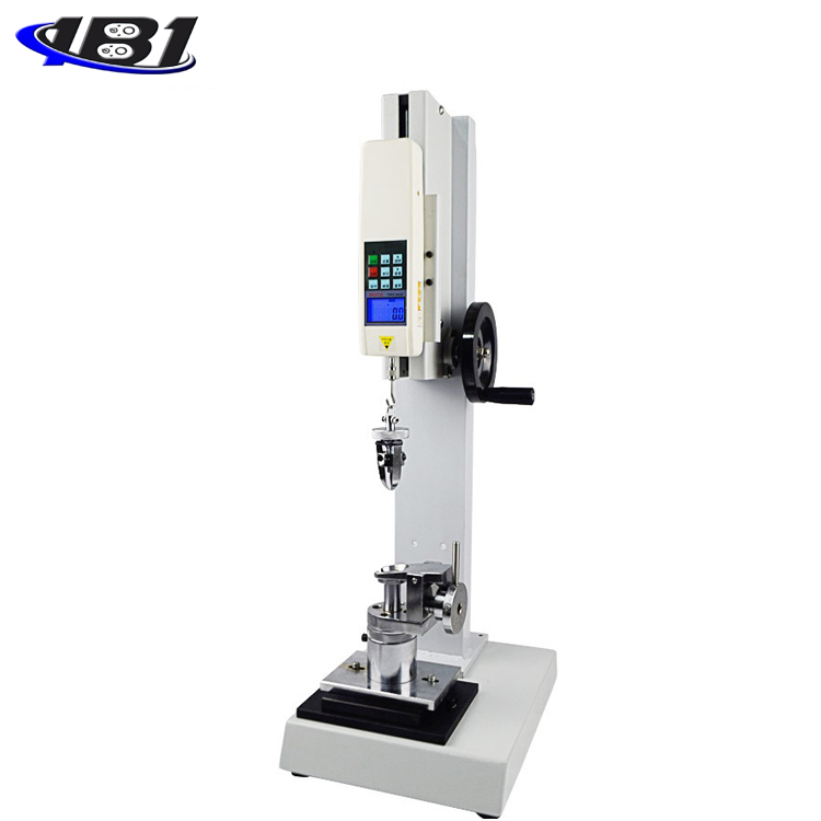
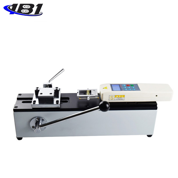
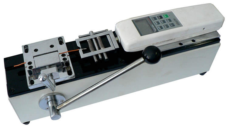
The terminal tensile tester is a testing device developed by our company for the wiring harness and electronics industry, and is specially used to detect the pull-out force of various wiring harness terminal blocks. It can be equipped with NK and HF push-pull force gauges and special fixtures. This instrument has the characteristics of compact equipment, accurate control, high measurement accuracy, easy clamping of test pieces, and simple operation.
Introduction to the instrument:
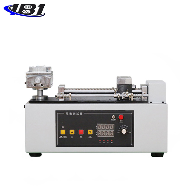
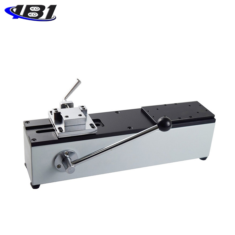
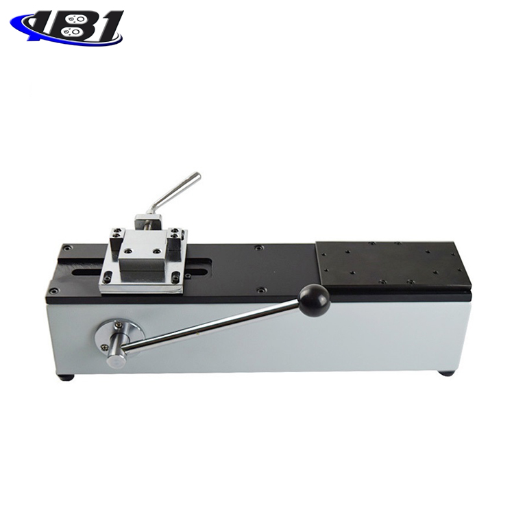
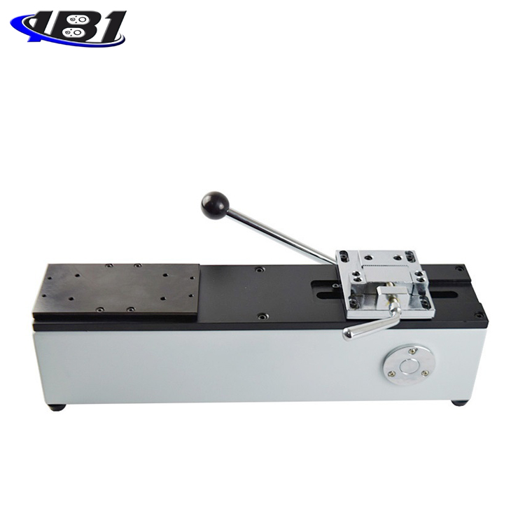
1. The base of the instrument (as shown below):

Horizontal installation.
· Manual operation, simple and stable operation.
· The machine can be installed on a table (table) to make the rack more stable.
· Length × Width × Height: 450mm × 260mm × 160mm.
· Effective stroke: 50mm.
· Rated load: 500N. (Also can be configured with 1000N)
· Net weight: 10.6Kg.
1. Push-pull force meter of the instrument:
The general standard configuration is a digital display push-pull meter HF-500. (Can also be equipped with pointer push-pull NK-500, different prices)
显 Digital display push-pull force meter
A. Model: HF-500.
B. Maximum load: 500N (Kg, N and ib three units can be converted automatically).
C. Resolution: 0.01N.
D. Accuracy: ± 0.5%.
E. Output interface: RS 232 nine-hole socket.
F. Power: Charging power: 220V / AC; continuous working time of battery: 6 ~ 8 hours.
G. Stability: Temperature drift: 0.2uV / ℃ (0 ~ 60 ℃); Zero drift: ≤ 0.1% / 8 hour / FS
H. Calibration range: full scale calibration.
I. Ambient temperature: 0 ~ + 60 ℃.
J. Ambient humidity: ≤ 80%.
K. Allowable overload: 150%.
L. Power supply mode: No. 5 nickel-cyanide battery pack / 220V AC for 4-6 hours.
指针 Analog push-pull gauge
M. Model: NK-500.
N. Maximum load: 500N (50Kg).
O. Push rod travel: 10mm.
P. Working temperature: 20 ℃ ± 10 ℃.
Q. Transport temperature: -27 ℃ ~ + 70 ℃.
R. Relative humidity: 15% ~ 80% RH.
S. Working environment: There is no vibration source and corrosive medium around.
Customers can configure dynamometers with corresponding specifications as required:
The pointer push-pull gauge specifications are NK-10, 20, 30, 50, 100, 200, 300, 500.
Digital display push-pull force gauge specifications are HF-2, 5, 10, 20, 50, 100, 200, 500, 1000 and so on.
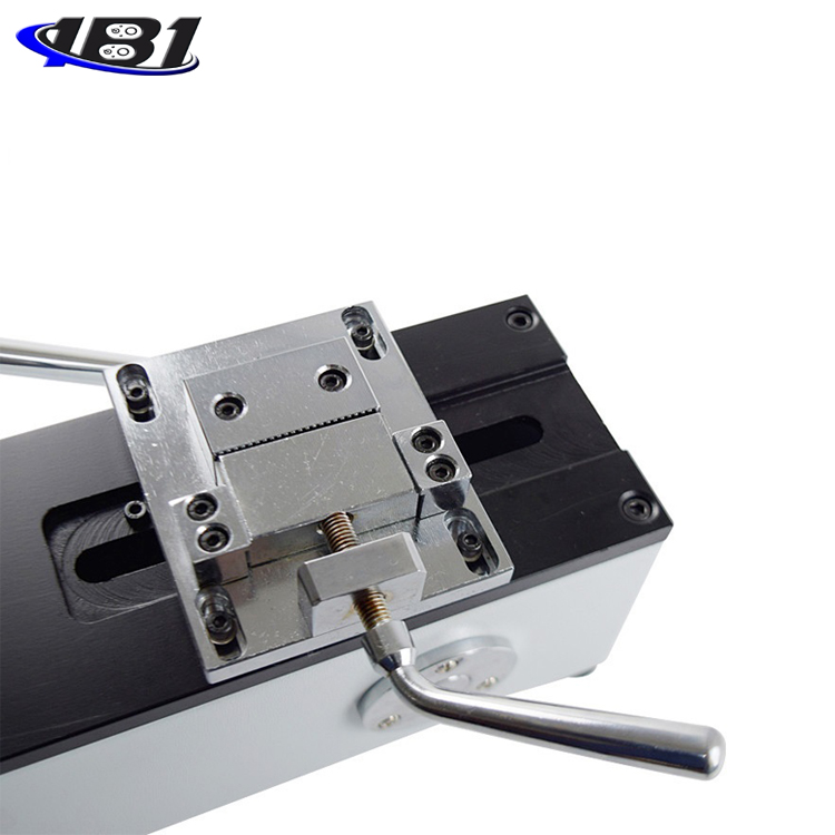
2. Left fixture of the instrument:
· Dimensions: 115mm × 180mm × 30mm.
· Scope of application: It is mainly used for pulling force testing such as plug-in and pulling-out force test, wiring harness terminal.
· Standard load: 500N, maximum load: 1000N.
3. Right fixture of the instrument:
· Model: AJJ-06.
· Scope of application: tensile, destructive, pluggable, wiring harness terminal testing of various cables, glass, leather, various electrical components and other materials.
Standard load: 500N, maximum load: 1000N
Third, the installation method of the instrument:
1. Mounting method of machine base:
The instrument can be installed on a table to make the instrument more stable. Please ensure that the work surface is level during installation so that the test can obtain accurate values. Please refer to the installation (length × width: 430mm × 80mm, 4 M4 threaded holes) for installation.
2. Installation method of push-pull force meter:
A. Use M4 wrench to loosen 4 M 4 × 16 hexagon socket head screws on the dynamometer mounting plate, and remove the dynamometer mounting plate;
B. Install the push-pull force timer of the HF series (digital push-pull force gauge), and use the M4 hex wrench to pass four M4 × 10 hex screws in the accessory bag through the 90 × 40 holes on the dynamometer mounting plate Screw into the 4 M4 threaded holes of the dynamometer and install the dynamometer on the dynamometer mounting plate; or use a Phillips screwdriver to pass 4 M3 × 10 cross recessed pan head screws in the accessory bag through the force Inside the meter, mount the dynamometer on the dynamometer mounting plate. The 145 × 30 holes on the mounting plate are screwed into the 4 M3 threaded holes of the dynamometer;
C. Install the push-pull force timer of the NK series (pointer push-pull force gauge), use a Phillips screwdriver to remove the four M × 10 screws on the back cover of the push-pull gauge, and remove the four M3 × 14 crosses in the accessory bag. The slotted screws pass through the 145 × 30 mounting holes on the dynamometer mounting plate and are screwed into the four M3 threaded holes on the back cover of the dynamometer (remove the screw holes of the M3 × 10 screws);
D. After the push-pull gauge is installed, reinstall the dynamometer mounting plate on the rack with an M4 allen wrench.
3. Installation method of left clamp:
Use an M4 hex wrench to insert the four M4 × 10 hex screws in the accessory bag through the four adjustment holes in the left clamp mounting plate into the four M4 threaded holes in the base plate of the machine. Machine base plate.
4. Installation method of right clamp:
First use the M6 nut in the attachment to screw the dynamometer's dynamometer rod, then turn the right clamp to the dynamometer's dynamometer rod, and adjust the M6 nut to make the right clamp one after another.
Fourth, the general test operation process:
1. Put the wire part of one end of various wiring harness terminals into the jaw of the left clamp, and rotate the handle to clamp the wire part (the wiring harness terminal has been pressed).
2. Put the other end of the wiring harness terminal into the jaw of the right clamp, and turn the handle to keep the wiring harness terminal locked in the middle.
3. Use an M4 Allen wrench to align the center of the left clamp with the center of the right clamp.
4. If you use the push-pull force timing of HF series (digital push-pull force meter), turn on the power and wait until the LCD display shows zero.
5. If the push-pull force timer of the NK series (pointer push-pull force gauge) is installed, press the switch button once to return the fingers to the zero position.
6. Rotate the handle of the fuselage to make the left clamp move to the left, and the right clamp can hold the terminal.
V. Daily maintenance and maintenance:
1. Do not overload the instrument. The rated load of this instrument is 500N.
2. Pay attention to daily maintenance work and keep all parts of the instrument clean.
3. When the machine fails, please contact the manufacturer or the sales point in time (do not disassemble or repair without permission).